Posts

Showing posts from March, 2016

First Booting : Raspberry Pi

Image
          Today, there are lot and lots of Development Boards are available in the home market. I picked the Raspberry Pi for several reasons. Raspberry Pi              Raspberry Pi (often called as R-pi) is the single board credit card sized computer with have a single System on Chip (SoC) board with the basic inbuilt computer features. It was developed by the Raspberry pi foundation in England. R-pi 2 model B           There are series of R-pi boards are available like(A/A+/B/B+/Zero/pi3) every new design overcomes the bugs in the older model.        Now I'm going to show how to setup your first Raspberry pi and loading the boot window. Hardware Required Raspberry pi Monitor Mouse & Keyboard Micro USB (5V/2A) Micro SD card (8GB Recommended) Micro SD to SD adapter HDMI to VGA converter Required Hardware  Software Required SD Formatter    Download Here NOOBS            Download Here         NOOBS is an New Out Of the Box Software which is an easy installer for the Raspbian
Electric saver circuit for TV and monitors

Image
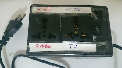
There are some electric appliances that must turn ON-OFF together in same time, for example TV and satellite or monitor and computer case,...etc, but sometime you forget one of them. By this circuit when you run the TV, the satellite turns on automatically and when you turns off the TV the satellite turns off automatically. The circuit is very simple, when an electric appliance with power consumption more than 10W running, the voltage through diodes 1N5408 increased and the optocoupler runs the relay for switching the second device. You can use this circuit for any other devices such as desktop computer parts. It help to electric consumption optimization. Parts list: Diode 1N5408(3pcs) Diode 1N4007 Zener diode 24v 1W Bridge diode 1A Optocoupler PC 817 Relay 12v Resistor 270 ohm 1W Capacitor 470nF 250v Capacitor 100uF 50v Capacitor 22uF 25v

Cable Glands for cable size; Flameproof and weather proof glands

Cable glands are used in cables for following purposes:- 1.        For removing strain in cable connections 2.        For providing earthing in case of armored cables 3.        They are used for providing cable entry into a panel. There are different types of glands available for different types of cables. Cables may be of armored type, Un-armored type. There are following types of glands are used:- 1.        Indoor glands- Brass Material 2.        Outdoor glands- Brass Material 3.        Unarmored cable glands- Brass material 4.        Weather proof glands/ Flameproof glands- Brass material 5.        PG threaded glands In Industries most widely armored cables are used. Gland sizes for these cables are as per below requirements:- Weather and flameproof glands are used in industries . Cables sizes and cable glands required are as below:- No. of cores Approx. overall diameter Double compression type Weather proof Flameproof Type 4C X1.5 mmsq 1

Oil Type Vs Dry Type Transformers

There are two types of Transformer depending upon type of medium used for cooling of Transformers:- 1.       Oil cooled/ Liquid Transformers 2.       Air cooled/ Dry Transformers In oil type transformers insulating oil (Mineral Oil) is used for cooling for Transformer winding. There are following advantages and disadvantages of both types of Transformers:- Oil Type Transformers Advantages:- (a)    Oil type Transformers are more efficient than Dry type Transformers (b)    Oil Type Transformers have usually higher life than dry type transformers (c)     In Oil type Transformers, Oil is better medium for cooling than air and thus reduces the hot spot in winding. (d)    Oil type Transformers overload capability than dry type transformers. (e)    For same rating Oil type Transformers have lower cost than dry type transformers (f)      Oil Type transformers have lower losses than dry type Transformers. In Oil type Transformers power losses are half than power losses in Dry Type transformers.

Password lock with only one button switch using Arduino

Image
Electronic locks with password always had a keyboard for inserting the code, but following lock used only one button switch. The code must inserts by pressing the button switch 5 times but with certain delay between each pressing, as you can see in programming code i sets this delay time 1 second delay between four first codes and 5 seconds for two last codes, you can change this code by changing that delay times in programming code. After inserting the correct code the load that connected to pin10 runs for 3 seconds, you can change this delay time in code. If an incorrect code inserts, the red LED turns ON also for 3 seconds. Last important note is the "tolerance" stage in programming code, i sets it on 0.4, that means the delay time between each two pressed buttons acceptable 40% more or lower than the delay time that you write it in the programming code, so 600 to 1400 milliseconds can accepted rather than 1000 milliseconds, or 3000 to 7000 milliseconds can accepted rathe

ELCB working principle; Difference between ELCB and RCCB/RCD

Earth Leakage Circuit Breaker or ELCB As clear from the name these circuit breakers are used for protection against electrical shock in case of leakage currents. ELCB get tripped whenever there are leakage currents in circuit. There are two types of ELCB’s:- 1.      Voltage ELCB 2.      Current ELCB Now let’s discuss the same:- 1.    Earth leakage circuit breaker Voltage Type:- As clear from the name these are voltage operated ELCB’s. These ELCB’s consists of relay coil . This relay coil is connected to the metallic body of equipment which is to be protected from earth leakage at one end and at other end it is connected to ground wire. If any fault occurs such as live wire touches the body than there will be voltage difference occur across the terminal of coil and earth. This voltage difference causes current to flow thus will operate relay and trips the ELCB. Voltage ELCB’s are available in various ranges these actuate as per limit described on ELCB’s. Voltage ELCB’s are no longer use

Wireless power transmission using Arduino UNO

Image
This is simple wireless power transmission that used Arduino UNO and power transistor. You can use any NPN power transistor such as TIP122 or 2N3055 or 13003 ... etc. Both coils are air-core with similar diameter and similar turns number (30 turns - 2 inches diameter). The output voltage in second coil is alternating (AC) so you have to use bridge diode to convert that to DC. For coil making you can use the chock coils wire of CFL lamp. you can also find the NPN transistor in CFL lamp (usually 13001 or 13003). Parts list: Bridge diode 1A NPN power transistor Capacitor 47nF(2pcs) 30 turns 2 inches diameter air-core coil(2pcs) LED 1.5 to 9v battery Resistor 100R In following video you can see how it works: Code: void setup() { pinMode(13,OUTPUT); } void loop() { digitalWrite(13,HIGH); delay(0.5); digitalWrite(13,LOW); delay(0.5); }