Posts

Showing posts from November, 2016

Global Systems (GSM) AT Commands

Image
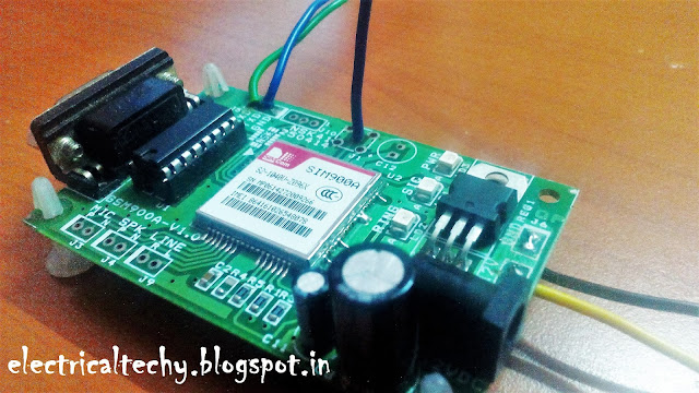
       Global System is a Protocol which is developed by the European Telecommunication Standard Institute (ETSI) to describe the II-Generation digital cellular devices. After a successful test in Finland. It is deployed to replace the Analog Communication (I-G) to the digital communication (II-G). Over 90% of mobile communication uses the GSM protocol to communicate and transfer the data. GSM Module               GSM module is a mobile communication modem, GSM is an open and digital cellular technology used for transmitting mobile voice and data services operates at the 850 MHz, 900 MHz, 1800 MHz and 1900 MHz frequency bands. In India the network providers almost provide in the frequency of 900 MHz. GSM MODEM AT Commands                AT commands which is traditionally called as AT tention commands which is used to communicate with the data transferring modules (Say: WiFi, Bluetooth, XBee, and of course GSM). It uses the two wire serial communication protocol. Modes of Communication

220V Auto room light switch using Arduino and Lazer (Visitor counter)

Image
Many peoples forgets the Room lamps in running state when nobody in the room, this causes increasing electric bill or battery energy losing in solar home. This Arduino project is a visitor counter that turns OFF the lamp when nobody in the room automatically, it also can used for lamps of bathroom, toilet, kitchen, etc. Visitor counter can makes by using different types of sensors, such as IR ray, Ultrasonic, Avoidance sensor, Laser ray, etc. Here i used Laser because the laser has long distance range, Avoidance sensor is very easy to use but its distance rang is lower than 30cm. You can make this project with LCD display for showing the numbers of people in the room but as you can see in the video i don't used display because its not important for me, any way the code is same with or without display. This project help to power consumption optimizing.  Parts list: Arduino board  1 Channel Relay module Laser diode(2 pcs) Light sensor modules(2 pcs) Adapter 5v 200mA If you want to us

AC 220V Frequency counter using arduino

Image
In this project i used Arduino and some other electronic components for AC mains frequency measurement. Since Frequency is equal to: 1 divided by time period, so in first we should measure the time period. Time Period is the time of one full wave in AC voltage, means positive half wave+negative half wave. Here i used optocoupler for detecting the frequency of AC voltage. 47K resistor decrease the current to about 5mA for running the optocoupler and one diode for half wave rectification  So the arduino here calculate the ON time and OFF time of optocoupler that connected to Pin 13 in arduino board, then divided 1 by ( ON+OFF ) Time for give the frequency.  Since in arduino code the time always must insert as millisecond so we devide 1000 by ON+OFF Time for give the frequency. The circuit 100% insulated from mains voltage and can not be harmful for your arduino board. You can use any other available optocoupler rather than 817B.  Parts list:  Arduino board LCD display 16x2 Resistor 10K R

Regenerative,Dynamic and Plugging braking

Brake obviously used to reduce the speed of any moving, rotating equipment’s. In day to day activity we use brakes in vehicles to stop them or reduce the speed of the same. We come through braking of 2 types:- (i)                   Electrical Braking (ii)                  Mechanical braking In mechanical braking speed is reduced by using mechanical process. But in electrical braking both electrical and mechanical systems are used for braking. Electrical braking system works on the principle of reversing the direction of flux. In most of systems motor is allowed to slow down and eventually stops after switching off the power supply of the motors. But for certain systems braking are needed to be provided. There are various types of motors such as Induction motors, DC motors, Single phase motors, And Synchronous motors etc. As these all types of motors are different from each other so type of braking method will also differ from each other. There are following type of electrical braking

Principle and Selection of electrical Chimney

Electrical Chimney is now becoming integral part of every house as houses are shrinking so to get natural ventilation becomes very difficult. Before purchasing chimney lot you have to carry out lot of research on internet so as to get best product as per your requirements. There are so many chimneys available in the market which can be selected as per requirements. It is always useful to look into technical specifications, prices , size etc. as per kitchen requirements.  Electrical chimneys are basically forced method of ventilation. All chimneys work on the principle of Updraft. Principle of Working of Chimney As Stated earlier that chimney works on the principle of updraft. Updraft is nothing but flow of air from bottom to top.  Pressure difference will created the required updraft. This required pressure difference is created by chimney.  Longer the height or length of pipe in chimney , longer will be the air is forced to travel through it. It must be kept in mind while designing c

Cable Tray Designing and Selection

Image
In electrical Systems for laying power cables , cable trays are preferable mode for laying cables over a long distance where digging can’t be feasible or digging cost is very high. Cable trays are also used where space is low. Also cable trays gives aesthetic looks to electrical systems. There are following recommendations for designing cable trays:- 1.      Always take 10-20% as Spare capacity. 2.      Distances between cables should be from 5 mm to 10 mm. Now let’s illustrate the same by taking an example:- Here we will design cable tray for aluminum cables:- (i)               10 no’s 2.5 mmsq X 4 Core cables (ii)              25 mmsq X 4 Core 10 no’s cables Calculation: For calculations following Table is used:- Total Outer Diameter : Diameter of 2.5 mmSq.mm Cable =No of Cable X Outer Diameter of Each Cable                                                        =10 X 16 = 160 mm Similarly for 25 mmsq cables = 25X10 =250 mm Total Diameter of All Cables laying in Tray = (160+250)mm=