Posts

Digital DC Voltmeter Using Microcontroller 8051 Mini Project

Image
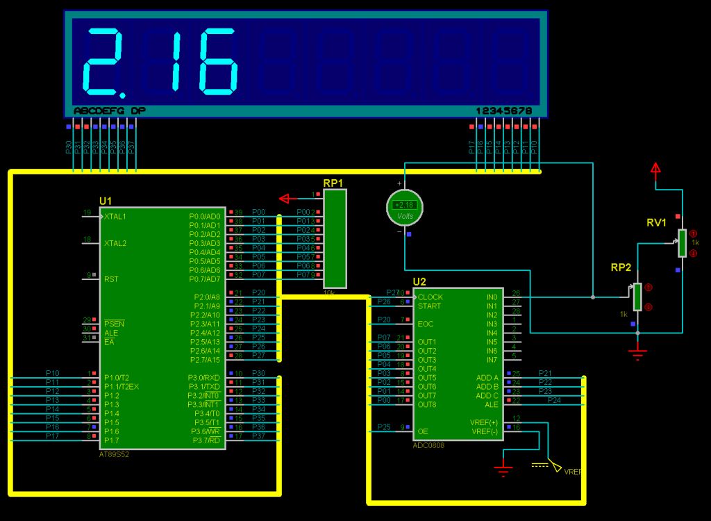
Digital DC Voltmeter Using Microcontroller 8051 Mini Project Digital DC voltmeter using Microcontroller or microprocessor is a project in which basically voltage of the system or circuit is measure and 7-segment or display on 16x2 Alpha numeric LCD(Liquid crystal display) This project is best suited for learning of voltage measurement and microcontroller or microprocessor based system from electronics or electrical field person or engineering or diploma student. In this project we are using digital measurement method in which we are uses ADC (Analog to digital convertor) to measure digital form of voltage and then processes this digital value using microprocessor or microcontroller 8051 from Atmel(89s52) then display this digital value on 7-segment or 16x2 Alpha numeric LCD. we can also use other microcontroller or microprocessor manufactures by NXP ARM, Microchip’s  PIC18f,PIC12F,PIC16F series…etc., STM series from STMicrotronics , freescale ,AVR etc. instated of Atmel 8

Wireless voltmeter using Arduino and RF 433MHz receiver and transmitter

Image
In this project i showed you how to make a wireless voltmeter using arduino and RF 433MHz receiver and transmitter. You can use this code and concept for many other projects, any project which used sensor with analog voltage output to sense temperature, gas leakage or light , etc. For example you can put a LM35 temperature sensor rather than potantiometer, you just have to putting its formula which convert LM35 output pin voltage to exact temperature. You also can make a wireless AC or DC power meter by doing some change in code and hardware (using hall effect current sensor and single phase voltage sensor). This type of RF module has distance range up to 200 meters according to datasheet but when i bought this RF module from Aliexpress its distance rang was very low, but i set its adjustable RF coil very carefully and i get very higher distance rang.(Don't play with RF coil if your module works good), You also have to use a 6 inch antenna to increase distance range to max as possi

MPU6050 | Live graph | Raspberry Pi

Image
Howdy! It's my pleasure to share my another work from my desk. Today I'm going to talk about interesting and important sensor. It's nothing but MPU6050 the combination of Accelerometer + Gyroscope + Temperature in a single board. It basically works with I2C protocol . Now, what we're going to do is interfacing MPU6050 with the Raspberry Pi and collect the real time data. And we're going to visualize the change in axis in the graph. Let's get started 💪 I've connected my MPU6050 and RPi with the hookups as mentioned. For visualizing the data I used python in combination with matplotlib. Working GIF 😉 Working Model It have lot of application. I look forward to hear it from you people.

Power factor measurment using Arduino

Image
In this project i used arduino and XOR gate to power factor measurement. What is power factor? Power factor is a number between 0 and 1 refers to phase shift between voltage phase and current phase in AC appliance. How to measure PF with Microcontroller (Arduino)? To measuring power factor with microcontrollers in first we used Op-Amp to zero cross detection to find the phase shift between current and voltage phase, the op-amp convert the sine wave signal comes from CT and PT with different amplitude to square wave with about 4v amplitude, then we connect these two square wave to XOR gate inputs.  XOR gate output will be 1 just when the input have different signal so when the load is resistive XOR gate output is 0 because both voltage and current phases start and ends in the same time, but when the load is inductive or capacitive XOR output is 1 because there are phase shaft between voltage and current, Hence we can find the power factor by measuring the "ON-time" of XOR out

Three power calculations from single phase and three phase loads

Three phase power calculations when you have Both Single and Three Phase loads in System:- While calculating three phase loads where  there are both single phase and three phase loads there are so many confusions arises such as how single phase and three phase loads comes at same platform while calculating total load. This is can be simplified in below stated article:- I n electrical systems power is always additive i.e. if we have connected load in each single phase of 20 KW then total three phase power requirement will be 60 KW. There is often confusion arises while studying that if you have Three phase power of 90 KW then it means power will be 90 KW in each phase but same is not true as it means power will be 30 KW in each phase. This can be illustrated by doing calculations in reverse order also:- Three Phase Power calculations for Line to Line Voltage:- Three phase power(KW) = √ 3  ×  PF  ×  I (A)   ×  V L-L  (V)  / 1000 Where PF= Power Factor I (A) = Phase current in Amperes V L

Motion Detection | OpenCV | Raspberry pi | Telegram

Image
Surveillance system is an important thing when it comes to protect our properties form the Intruders👀. Here is an simple project which can able to protect your belongings form the intruder. Let get started.💪 First of, we need a camera and the DVR setup. But thankfully Raspberry Pi in combination with the OpenCV does the job for us. I used the motion detection technique provided by Mr.  Adrian Rosebrock  from pyimagesearch.com to fulfill my requirement.  To get the notification when the Intruder is detected. We should push the data to cloud and retrieve it form the location uploaded. It's a long process and took time to build an universal application. So I used a commonly used messaging application called telegram and it's an cross platform application. Voila! The wait is done. Once I run the program, It capture the motion and send the real time image to mobile phone. Snaps Working Snaps Telegram Message PoC Hope this concept will embed into the existing DVR's. Bye for now