Posts

Showing posts from March, 2015

1.5v LED flasher

Image
This circuit is a LED flasher that run by 1.5v AAA battery. Flashing speed can change by changing C1. The circuit consume low current, 20mA when LED be turn ON. Parts list: Transistor BC547 Transistor BC557 LED Resistor 680ohm (2pcs) Resistor 39 ohm Resistor 330K Capacitor 10nF Capacitor 2uF Capacitor 470uF 1.5V Battery

Simple emergency light

Image
Following circuit is a simple emergency light. when it connected to power supply(adapter) the battery be charged and when the electricity be turn OFF or the adapter be disconnected the LEDs be turn ON automatically . its cheap, simple and useful. you can use a power LED rather than use several LEDs. R2 must be jumped when a power LED used. (as you see in follow video)

Timer with touch switch

Image
This circuit is a timer that turn ON by touch. When you touch leg 2 of IC the load be turn ON and after 3sec to one hours or more the load be turn OFF.(this period can adjustment by the potentiometer) You can increase this time period by increase the value of capacitor.

How to make a simple light meter

Image
Following circuit is simplest light meter that made by one NPN transistor,LDR and voltmeter  have good sensitivity to light. you can run it by 5 to 30 volt (according to type of voltmeter)

Transparent Energy

Image
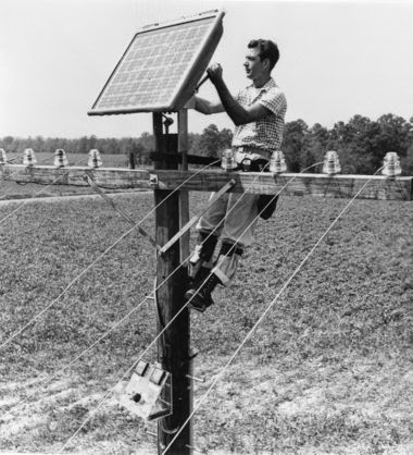
   There are currently many research groups active in the field of photovoltaics in universities and research institutions around the world. This research can be divided into three areas. Making current technology solar cells cheaper and more efficient.  Developing new technologies based on new solar cell architectural designs. Developing new materials to serve as light absorbers and charge carriers. Ancient Solar Module But the recent development is...         Many new solar cells use transparent thin films that are also conductors of electrical charge. The dominant conductive thin films used in research now are transparent conductive oxides (abbreviated "TCO"), and include fluorine-doped tin oxide (SnO2:F, or "FTO"), doped zinc oxide (e.g.: ZnO:Al), and indium tin oxide (abbreviated "ITO"). These conductive films are also used in the LCD industry for flat panel displays. The dual function of a TCO allows light to pass through a substrate window to the ac

Simplest PWM DC motor speed controller

Image
PWM DC motor speed controller use in different area such as cordless drill, children car, solar car, etc. following circuit is simplest PWM DC motor speed controller made by IC 555 and  MOSFET. you can use other N-channel MOSFET such as IRZ46N or IRF520 you must use heat sink for MOSFET    

Simple password circuit using IC 4017

Image
This is a simple password circuit that can run any electric device when a true password inserted the circuit based on IC counter 4017 that used in sequentially LED flasher and other applications. When you press S1 then S2 then S3 then S4 the relay be turn ON otherwise the relay stay turn OFF. the keys that connected to pin 15 of the IC reset the circuit so if you pressed 2 first pass code correctly by pressing any false key the circuit reset the first correct codes. you have to configuration the S1 to S4 as you want for example if you want to make the password 7460 so you have to connect S1 to number 7 in the keypad and S2 to number 4 and S3 to number 6 and S4 to number 0 in the keyboard. in following video you can see how it work. Parts list: IC4017 Relay 12v Transistor 2N3904 or any other NPN transistor Diode 1N4007 Diode 1N4148(5pcs) Capacitor 100uF Resistor 100K(2pcs) Resistor 10K Resistor 1K Push button switch(10pcs) LED

Traffic light using IC4017

Image
This circuit is a simple traffic light, composed of IC 4017 and IC 555 The speed can change by P1 you can add more LEDs for each color Parts list: IC 4017 IC 555 Diode 1N4007 (9pcs) Potentiometer 1M LEDs(12pcs for each color) Capacitor 10uF 25v Resistor 100k

The Beagleboard

Image
The BeagleBoard is a low-power open-source hardware single-board computer produced by Texas Instruments in association with Digi-Key and Newark element14. The BeagleBoard was also designed with open source software development in mind, and as a way of demonstrating the Texas Instrument's OMAP3530 system-on-a-chip. The board was developed by a small team of engineers as an educational board that could be used in colleges around the world to teach open source hardware and software capabilities. It is also sold to the public under the Creative Commons share-alike license. The board was designed using Cadence Or CAD  for schematics and Cadence Allegro for PCB manufacturing. No simulation software was used.   See more about it. Logo

Power factor Improvement formula; Additional KVAR required for Power factor improvment.

Every industry monitor its power factor so that they will not pay for reactive power at lower factor. It become very important to know what additional capacitor bank required for improvement of power factor. Every industry consists of inductive load such as lights and motors which usually have power factor in the range to 0.8 to 0.85. So power factor improvement is of prime importance as if they kept running their system at same power they suffer loss of 20 to 15%. As if they keep power factor at 1 they will not have pay any additional charges at lower power factor. So let’s calculate what additional capacitor bank needed for power factor improvement. Let’s take an example that system is running at 0.8 power factor and inductive load is 200 KW what additional capacitor bank required for improvement of power factor from 0.8 to 1. KVAR Required = KW X [tan (cos -1 (running P.F)- tan (cos -1 (Desired P.F)] Now KW is 200 KW and running P.F. is 0.8 and desired PF is 1 putting these value

Electricity bill understanding/ Electricity bill simplified

Image
Usually understanding electricity is made very simpler by power distribution companies. Whenever new electricity bill received then everyone reads through it to come to know what is the unit consumption this month and whether this consumption is increasing or decreasing everyone uses some trend analysis. There are some certain terms which should everyone know before understanding electricity bill. Before going in details please look at the bill mentioned above. Sanctioned Load When you look at the bill at the top most there is Name and address is printed on the bill. Then there is Sanctioned load which indicates what is the load sanctioned for Industrial or domestic customers. This is usually sanctioned depending upon load connected at the system . Maximum Demand Indicator Then there is MDI means Maximum demand indicator which indicates the Maximum demand for the current month billing period this Maximum demand should not exceed Sanctioned load. For Industrial customers if this maximum

Sequential LED flasher by IC 4017

Image
The following circuit is  sequential flasher with 10 LEDs Can change its speed by changing the value of capacitor or 33K resistor circuit is composed of two parts, the first part IC 555 which generates a clock pulse, and the second part is IC 4017 running LEDs sequentially Can run the circuit by 3 to 9 volts a nd it draw 10mA current. 470 ohm resistor used for LED protection. Parts list: IC4017 IC555 LEDs(10pcs) Resisto r 470 ohm R esistor 33K Capacitor 2.2uF