Posts

Showing posts with the label LED projects

Wireless power transmitter using IC555
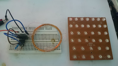
Image
This is a wireless power transmitter that used IC 555 and power transistor. I used it for running 36 white LEDs. You can use any other NPN power transistor instead of 13003. Both coils are 30 turns enamelled wire 30 SWG with 5cm diameter. 10 ohm resistor that placed between base of transistor and pin3 of IC, can replaced by 5 to 75 ohm resistor or jumped, if you jumped it the max. distance range between two coils increased.(power consumption also increased) The circuit run by 3v battery and power consumption is 80 to 270mA. Parts list: IC555 Transistor 13003 Coils 30 turns, 5cm diameter, 30 SWG wire Capacitor 3.3nF Capacitor 47nF Resistor 1k Resistor  10 ohm Resistor 10k LEDs Battery 3v
Simplest LED chaser using IC4017(without timer IC)

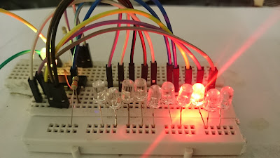
Image
LED chasers that using IC4017 always contain a timer ic for making clock pulse, but this circuit used a flashing RGB LED as a pulse source, so this is simplest, smallest and cheapest LED chaser with 10 LEDs. This circuit can run with 9v battery and draw only 20mA.  Parts list: IC4017 LEDs(10pcs) Flashing LED Resistor 470 ohm Resistor 330 ohm Battery 9v

1.5v LED flashlight circuit

Image
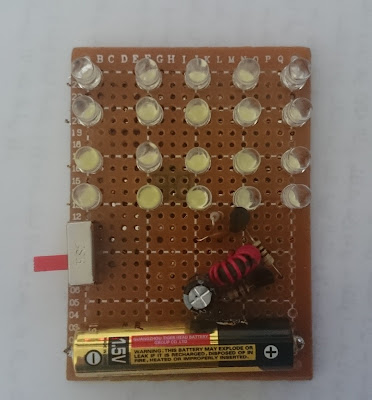
This circuit is an LED flashlight that can run with 1.5 volt AAA battery. this circuit is easiest for beginners because the coil is available in CFL lamps circuit and don't need to make that. I used it for running 20 white LEDs, you can add more. By 20LEDs it draw about 100 to 200mA current from battery. Minimum voltage that need to run LEDs by this circuit is about 0.9v. I test this circuit with different coils and i find the circuit works perfectly with almost all ferrite coils , so you can make that with any available ferrite coil and maybe give better results. Parts list: White LED(20pcs) Transistor S9012 Transistor S9013 Coil 100uH Capacitor 500pF  Capacitor 220uF 10v Resistor 5.6k Resistor 10k Resistor 100 ohm 1.5v AAA battery The following picture show you the coil that available in each CFL lamp, the big coil  in right side give you better result than that circular small coil and maybe can run more than 100 LEDs easily.

LED flasher using Arduino Nano and 132 LEDs

Image
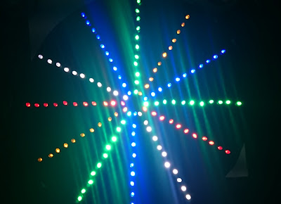
This is flower shaped LED chaser using Arduino Nano and 132 LEDs. Each LED bar contain 11 LEDs, connected together in parallel, and used 100 ohm resistors for LEDs protection. Parts list: 1-Aluminum plate with 0.7mm thickness 2-Drill bit 5mm(for 5mm LEDs) 3-LEDs 5mm blue, white, red, green, yellow  4-Black color spray 5-100 ohm resistors 6-Connecting wire 7-Arduino Nano 8-Power supply 5v 500mA You can change the flashing speed by changing the number that written after "delay" in the programming code. void setup(){   pinMode(2, OUTPUT);   pinMode(3, OUTPUT);   pinMode(4, OUTPUT);   pinMode(5, OUTPUT);   pinMode(6, OUTPUT);   pinMode(7, OUTPUT);   pinMode(8, OUTPUT);   pinMode(9, OUTPUT);   pinMode(10, OUTPUT);   pinMode(11, OUTPUT);   pinMode(12, OUTPUT);   pinMode(13, OUTPUT); } void loop(){     digitalWrite(4, HIGH);   delay(100);   digitalWrite(4, LOW);   delay(100);   digitalWrite(4, HIGH);...

Running 70 LEDs by 1.5v AA battery

Image
By this circuit you can run more than 70 LEDs by an AA battery. The circuit draw 100 to 200 mA from the battery. you can find the choke coil from a mobile charger or old flash camera or rechargeable fly zapper. Parts list: Transistor 2N2222 Resistor 1k Chock coil LED(70pcs) Battery 1.5v NOTE: 1-test the output voltage before connecting that to the parallel LEDs. (2-3v is good) 2-using bigger transformer(choke coil) and power transistor maybe raise the output voltage up to 100v.    

Distance meter with 6 LEDs using arduino and ultrasonic sensor

Image
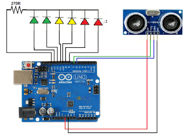
This is simple distance meter with 6LEDs. you can replace the last red led with a buzzer. distance range: <5 to 30cm ultrasonic module: HC-SR04 NOTE: Ultrasonic module can detect distance range from 2cm to 450cm but in this project i set the distance range from <5 to 30cm. code: #define trigPin 7 #define echoPin 6 #define led 13 #define led2 12 #define led3 11 #define led4 10 #define led5 9 #define led6 8 int sound = 250; void setup() {   Serial.begin (9600);   pinMode(trigPin, OUTPUT);   pinMode(echoPin, INPUT);   pinMode(led, OUTPUT);   pinMode(led2, OUTPUT);   pinMode(led3, OUTPUT);   pinMode(led4, OUTPUT);   pinMode(led5, OUTPUT);   pinMode(led6, OUTPUT);   } void loop() {   long duration, distance;   digitalWrite(trigPin, LOW);   delayMicroseconds(2);   digitalWrite(trigPin, HIGH);   delayMicroseconds(10);   digitalWrite(trigPin, LOW);   duration = pulseIn(echoPin, HIGH);   distance = (d...

How to make LED board (method 2)

Image
This is second method for making LED board. in first method i used breadboard for making a small LED board but since there aren't big breadboard in markets so that method not suitable for big size projects. In following video you can see how can make a LED board using aluminum plate. The aluminum plate with 0.7 mm thickness must puncture with 4.8 or 4.9 mm drill bit.(for 5mm LEDs) The LEDs must connect together in parallel means all positive connect together and all negative connect together so you can run that with 2 to 3.5v (according to led types). you have to using a resistor through positive line to protect your LEDs and increase its life period.(see the note) Parts list: Aluminum plate 0.7 mm thickness Drill bit 4.8 or 4.9 mm (for 5mm LED) Silicone adhesive Black color spray battery Text or shape printed on a paper Solder flux LED(number of LEDs depend on your text or shape bigness) Resistor (see the note) Note:  Protection resistor used when supply power is more than s...

Running LED by 220v

Image
This circuit is simple way to running some parallel LEDs by direct 220v. The output current depend on the capacitor and the resistor and can calculate from following equations: The series capacitor in AC current work as a resistor called (Capacitive reactance) in first you have to find it from following formula: Xc = 1 ÷ (2Ï€ * f * C) Where: Xc is the Capacitive reactance in ohm f is the frequency of mains voltage in Hz(usually 50 or 60Hz) C is the capacitor value in Farad V is mains voltage Then add this Capacitive reactance to the resistor to find total resistor (Z): Z= √( (Xc^2)+(R^2) ) Now you can use Ohm's law for finding output current: I = V ÷ Z EXAMPLE: Find the output current for following circuit? Xc = 1 ÷ (2Ï€ * f * C) Xc = 1 ÷ (2Ï€ * 50 * 0.0000001) Xc = 31847.1 Ohm Z= √((Xc^2) + (R^2)) Z= √((31847.1^2) + (150^2)) Z= 31847.4 Ohm I = V ÷ Z I = 220 ÷ 31847.4 I = 0.00697A = 7mA Since 5mm LEDs need to 5 to 10mA for running so this capacitor and resistor value is enough to runn...

How to install and programming an LED sign board

Image
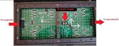
Each LED board contain 3 basic parts: LED module, controller, power supply LED module LED modules can connect together to make a big display. there are single color LED modules, 2colors and full colors(RGB) LED modules. since traditionally LEDs when leaves in sunlight for long time loss its first brightness, so that modules make by special LEDs that have higher resistance to sun ray.   Controller controller (some time call mother board) contain LED display driver, memory and back up battery. Power supply power supply is a 5v regulated adapter and its current is between 1A to 50A or more (according to number of modules that make bigness of display) Note: connecting + and - in reverse causes damage for both controller and LED modules. Programing process For programming the LED board first must install "HD2013" program on your computer. You can download it from following link( password=168 ): https://drive.google.com/open?id=0B4jg9KxpTKGTeWZzbU11Yl82cG8 when installing comple...

Sound detector with LED

Image
This circuit is a Sound detector that run a LED when detect voice. can use as voice level detector or anti theft system. the circuit can run by 6 to 12v.    

Audio VU meter with 8 LED

Image
This circuit is an audio VU meter. it run by 6v to 12v. the sensitivity can change by the potentiometer. you can add more LEDs by adding further IC.

Traffic light using IC4017

Image
This circuit is a simple traffic light, composed of IC 4017 and IC 555 The speed can change by P1 you can add more LEDs for each color Parts list: IC 4017 IC 555 Diode 1N4007 (9pcs) Potentiometer 1M LEDs(12pcs for each color) Capacitor 10uF 25v Resistor 100k

How to make LED board (method 1)

Image
LEDs because of the diversity of colors, strong lighting and consume little power used in many areas, can use for write letters and draw shapes. In following video you can see how it can. The LEDs must connect together in parallel, means all positive connect together and all negative connect together so you can run that with 2 to 3.5v (according to led types). you have to using a resistor through positive line to protect your LEDs and increase its life period.(see the note) you can use second method for big LED boards . Parts list: Breadboard (25cm x 12cm) battery Text or shape printed on a paper Solder flux LED(number of LEDs depend on your text or shape ) Resistor (see the note) Note:  Protection resistor used when supply power is more than standard LEDs voltage , its value depends on number of LEDs, LEDs type(color) and voltage of battery or power supply.  You have to using ohm's law for calculation the value of necessary resistor. in first run your LED board by 2 to 3v ba...