Posts

Showing posts from June, 2014

Fan Regulator; Function of fan regulator ; Why Fan regulator required
Image
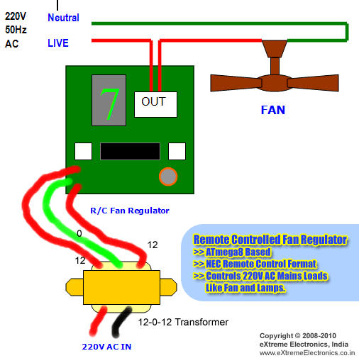
A fan regulator is an important element that functions to raise or reduce the rate of your fan according to your own demands. You've got a choice between electronic and traditional regulators. Regulators Standards Older variants of traditional regulators were rather bulky to examine. A square carton jutting from a plank with a ring-shaped toggle or knob switch failed to make for quite glossy look. The box included the circuit components of the regulator system. You'd to fix the knob to place the fan at the desired rate. Modern day only a toggle is presented by standard regulators on a panel that includes the switches for the other electrical devices. You may not really get to see the modulating unit hidden in the wall behind the plank. You must know something to comprehend how a regulator functions. The conductor nevertheless, offers a specific amount of opposition to the passage of current. The resistance is determined by the substance of the conductor. The regulator has spool

Why Power Transmission is done at Very High Voltages?

After generation of electricity it is important to transform that voltage at user end/ load end. Reason 1 for Transmission at Higher voltage During transmission there are losses known as Transmission losses as heat get generated during transmission, Usually this loss is known as heat loss. Heat loss is = I 2 R When Transmission is done at High voltage then Current drawn will get reduced as:- Transmission power= Voltage X Current X Power factor Now Current=   Transmission Power                           Voltage X Power factor From above you will see that higher the transmission voltage, lower will be the Current so lower will be I 2 R losses. Now let’s take an example; For Power transmission at 11 KV and 33 KV for power of 1 MW, in both cases resistance will be same so only variable is Transmission voltage. Current(11KV) = Transmission power (1 MW) ----------  (i)                             11 KV X Power factor Current (33 KV) = Transmission power (1 MW) ---------   (ii)              

Voltmeter and Ammeter working principle; Moving iron type instruments working principle

Image
Basic principle and building process of Voltmeter and Ammeter devices Ammeter and Voltmeter as everyone knows are devices which are typically used to measure alternating currents and voltages. In moving-iron devices the movable system includes a number of pieces of specially-molded soft iron, as to be acted upon by the magnetic field created by the current which are thus pivoted. Basic circuit by which Voltmeter and Ammeter are connected is as shown below:- You will find two general kinds of proceeding-iron devices specifically: 1. Attraction (or single-iron) 2. Repulsion (or double iron) The simple description of distinct parts of a moving-iron device is given below: 1.   Moving component :     a little piece in the shape of pole or a vane. 2.   Coil:     to magnetize the iron pieces and to create the magnetic field as a result of current flowing through it. In repulsion kind, stick or a set vane can also be used and magnetized with the exact same polarity. Control torque is supplie

Effects of High Voltage on Human body; High voltage effects oh Human Body

Introduction There is always need for transmission of Very high voltages as electricity demand is kept on increasing day by day. Big transmission lines shapes with current and high voltage amounts create substantial values of magnetic fields and electric stresses which influence the nearby items found at earth surfaces and the human being. This must be investigating the effects of electromagnetic fields. Besides electromagnetic noise, the electrostatic coupling & human effect have impact on telecommunication equipment's and plants primarily working in frequency range. It is the controversy Discussion right eludes on Power Company and Government Management policy. There are a lot of criticize this arguments and supporting records and research paper. Magnetic and electrical fields, frequently called EMF or electromagnetic fields, appear naturally and as an outcome of the Electricity generation, Power Transmission, Electricity distribution and use. . Electrical voltage and current

Understanding Neutral,Neutral connections, fault current paths, and grounding

Understanding Neutral Neutral is the common reference point in electrical systems with respect to whom all voltages are measured. Neutral in electrical system is used to carry unbalance currents. Neutral is generally grounded so to get rid of the unbalance voltages generated in electrical systems. In single phase systems Neutral is used as return path. In Three phases it is used for carrying unbalance voltages. With introduction of Non-linear loads such as PC’s, TV’s, and other electronic equipment’s requirement of neutral is increased considerably. Neutral connections:- In case of star connections neutral is common point of all three phases connections. In delta connections there is no need for neutral. Usually delta-star connections are used in Transformers so as to get neutral for domestic and industrial supplies. Neutral flow in conjunction with all three phases.  In MCCB’s also neutral is provided without overload protection so as to bypass all fault current without affecting MCC

Concept and Nature of electricity

Image
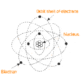
Electricity is the most essential for every human being as electricity is now an incorporate part of everything these days. It appears to really significant part every life. Electricity can be used for various programs such as 1. Businesses 2. Light 3. Cooking 4. Communicating 5. Transport None of us just understand that what's electricity. The theory and theories can be developed by discovering its  behaviors  that were distinct. It's important to examine the arrangement of matters, for discovering nature of electricity. Every material in this universe consists of incredibly small particles called molecules. The molecules comprise of farther smaller particles called atoms. You will find two kinds of materials. The material, that is molecules are manufactured from atoms that are similar is called an element. The matter is called a compound. The theory of electricity is possible in the atomic arrangements of materials. Construction of Atom An atom contains one central nucleus. T

Instrument transformers working principle; Current Transformer ; Potential Transformers

Instrument transformers means for stepping down voltages and currents of the system for metering and protection function voltage transformer & current transformer are used. Really meters and relays used for metering and protection, aren't designed for voltages and high currents. Voltages or high currents of electrical power system cannot be right fed to meters and relays. CT measures down rated system current or 5 Amp likewise voltage transformer measures down system voltages Meters and the relays are typically designed for 5 Amp, 1 Amp and 110 V. Definition (CT) A CT is an instrument transformer where the secondary current is considerably proportional and differs by degree that is ideally zero in phase. CT Current Transformer Category or Precision Class A CT is not dissimilar to an electrical power transformer somewhat, but there are a lot of difference in operation and building principle. For sign and metering function, correctness between secondary and primary currents are n