Posts

Showing posts with the label LED flasher and chaser

LED chaser with only one IC555
Image
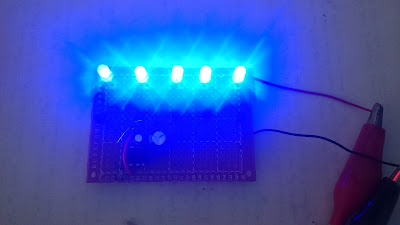
This circuit is a simple LED chaser, (Bike Turning Signal Circuit) used IC 555 and 5 transistors. Here we used IC 555 as astable multivibrator to running the transistors. Flashing speed depend on both capacitors. 1K resistors used for each LED as protection. The circuit run with 12v and draw 40mA current when all LEDs be turn ON. Parts list: IC555 LEDs(5pcs) Transistor S9013(5pcs) Diode 1N4148 Capacitor 470uF Capacitor 100uF Resistor 1K (6pcs) Resistor 4.7K (2pcs) Resistor 10K (2pcs) Resistor 680 ohm
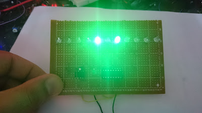
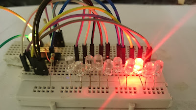
Sequential LED flasher using IC 4017 (KNIGHT READER)

Image
This is a beautiful sequential LED flasher (LED chaser) that also called KNIGHT READER CIRCUIT. Flashing speed can changed by changing the value of capacitor or 33K resistor.  The circuit run by 5v and draw very low current lower than 10mA. You can run the circuit by 12v battery but you have use 1K resistor rather than 470ohm resistor to LED protection. Parts list: IC4017 IC555 Resistor 470 ohm Resistor 33K Diode 1N4148(8pcs) Capacitor 2.2uF LEDs(11pcs)  

Simplest LED chaser using IC4017(without timer IC)

Image
LED chasers that using IC4017 always contain a timer ic for making clock pulse, but this circuit used a flashing RGB LED as a pulse source, so this is simplest, smallest and cheapest LED chaser with 10 LEDs. This circuit can run with 9v battery and draw only 20mA.  Parts list: IC4017 LEDs(10pcs) Flashing LED Resistor 470 ohm Resistor 330 ohm Battery 9v

12v power LED flasher circuit using RGB flashing LED

Image
Flasher circuits usually using 2 transistors or IC, but this circuit used a RGB flashing LED as flashing pulse generation. You can use any other NPN transistor but must pay attention to its max. switching current, according to current of LED(load) . Parts list: RGB flashing LED Transistor S8050 Resistor 100 ohm Resistor 1k Power LED 12v

LED flasher using Arduino Nano and 132 LEDs

Image
This is flower shaped LED chaser using Arduino Nano and 132 LEDs. Each LED bar contain 11 LEDs, connected together in parallel, and used 100 ohm resistors for LEDs protection. Parts list: 1-Aluminum plate with 0.7mm thickness 2-Drill bit 5mm(for 5mm LEDs) 3-LEDs 5mm blue, white, red, green, yellow  4-Black color spray 5-100 ohm resistors 6-Connecting wire 7-Arduino Nano 8-Power supply 5v 500mA You can change the flashing speed by changing the number that written after "delay" in the programming code. void setup(){   pinMode(2, OUTPUT);   pinMode(3, OUTPUT);   pinMode(4, OUTPUT);   pinMode(5, OUTPUT);   pinMode(6, OUTPUT);   pinMode(7, OUTPUT);   pinMode(8, OUTPUT);   pinMode(9, OUTPUT);   pinMode(10, OUTPUT);   pinMode(11, OUTPUT);   pinMode(12, OUTPUT);   pinMode(13, OUTPUT); } void loop(){     digitalWrite(4, HIGH);   delay(100);   digitalWrite(4, LOW);   delay(100);   digitalWrite(4, HIGH);...

81 LED chaser using double IC 4017

Image
This circuit is LED chaser using double IC 4017 and IC 555 with 81 LEDs. Flashing speed can change by potentiometer. All transistors are 2N3904 but you can use any other NPN transistor. Diode 1N4007 used for inverse power connection protection because IC 555 is very sensitive to - and + power supply reverse connection. 470 ohm resistor used for LEDs protection. you can use different color for each LED column. The circuit can run by 3 x AA battery and power consumption is very low (about 10 to 20mA). Parts list: IC4017(2pcs) IC555 2N3904(9pcs) 10k resistor(10pcs) 470 ohm resistor 3.3k resistor LED(81pcs) Capacitor 1uF 10v 100k potentiometer  Diode 1N4007 1.5v AA battery(3pcs)

Amazing LED chaser with 12 LEDs using arduino

Image
This is an amazing LED chaser that contain 12 LEDs. Each LED must protect by a 100ohm resistor. the speed of flashing can change by changing the number that written after "delay" in the programming code. void setup(){   pinMode(2, OUTPUT);   pinMode(3, OUTPUT);   pinMode(4, OUTPUT);   pinMode(5, OUTPUT);   pinMode(6, OUTPUT);   pinMode(7, OUTPUT);   pinMode(8, OUTPUT);   pinMode(9, OUTPUT);   pinMode(10, OUTPUT);   pinMode(11, OUTPUT);   pinMode(12, OUTPUT);   pinMode(13, OUTPUT); } void loop(){     digitalWrite(4, HIGH);   delay(100);   digitalWrite(4, LOW);   delay(100);   digitalWrite(4, HIGH);   delay(100);   digitalWrite(4, LOW);   delay(100);   digitalWrite(8, HIGH);   delay(100);   digitalWrite(8, LOW);   delay(100);   digitalWrite(8, HIGH);   delay(100);   digitalWrite(8, LOW);   delay(100);   digitalWrite(2, HIGH);   delay(10...

1.5v Flasher with 25 LEDs

Image
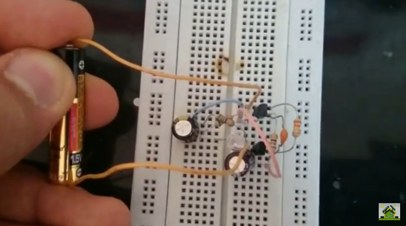
This is an amazing LED flasher that run by only 1.5v AA battery. The circuit based on joule thief method. main circuit was designed by handmade choke coil but i change that to this new circuit that don't need to coil making because that was very difficult. you can use an electric zapper choke coil. the flashing speed can change by potentiometer. A new 1.5v alkaline battery can run this circuit for more than 30 hours(by lowest flashing speed). I test this circuit by 25 LEDs but you can add more. Zapper choke coil usually have 6pin and 3 internal coil. in first you should determine that by an ohmmeter, then put that in the circuit. the temperature of  transistor raise in high speed flashing, so need to a heatsink.  Parts list: Transistor 2N2222 Resistor 100 ohm Potentiometer 1k Capacitor 100uF 35v Chock coil of old camera or electric zapper or mobile charger Battery 1.5v AAA or AA LED Diode 1N4007 Diac DB3  

Sequential flasher using arduino and 14 LED

Image
This is simple flasher with 14 LEDs. you can decrease the flashing speed by changing number "100" in first line of program code to "500" for example. You must protect your LEDs by putting a 150 ohm resistor through GND line. Code: int timer = 100;      int ledPins[] = {   0, 1, 2, 3, 4, 5, 6, 7, 8, 9, 10, 11, 12, 13};     int pinCount = 14;       void setup() {   for (int thisPin = 0; thisPin < pinCount; thisPin++)  {     pinMode(ledPins[thisPin], OUTPUT);       } } void loop() {   for (int thisPin = 0; thisPin < pinCount; thisPin++) {     digitalWrite(ledPins[thisPin], HIGH);      delay(timer);                     digitalWrite(ledPins[thisPin], LOW);     }   for (int thisPin = pinCount - 1; thisPin ...

Randomly flasher

Image
This circuit is a randomly flasher that can use as Christmas tree flasher you can add many LEDs in each branch can run it by 5 to 12v according to number of LEDs in each branch. 390 ohm resistor used to LEDs protection. Parts list: IC 4060 LEDs Capacitor 10nF(0.01uF) Resistor 390ohm Resistor 100K Resistor 2.2M Potentiometer 1M  

1.5v LED flasher

Image
This circuit is a LED flasher that run by 1.5v AAA battery. Flashing speed can change by changing C1. The circuit consume low current, 20mA when LED be turn ON. Parts list: Transistor BC547 Transistor BC557 LED Resistor 680ohm (2pcs) Resistor 39 ohm Resistor 330K Capacitor 10nF Capacitor 2uF Capacitor 470uF 1.5V Battery

Sequential LED flasher by IC 4017

Image
The following circuit is  sequential flasher with 10 LEDs Can change its speed by changing the value of capacitor or 33K resistor circuit is composed of two parts, the first part IC 555 which generates a clock pulse, and the second part is IC 4017 running LEDs sequentially Can run the circuit by 3 to 9 volts a nd it draw 10mA current. 470 ohm resistor used for LED protection. Parts list: IC4017 IC555 LEDs(10pcs) Resisto r 470 ohm R esistor 33K Capacitor 2.2uF    

220v LED flasher

Image
The following circuit is Flasher which operates by 220 volts you can add many LED lights in various colors in parallel advantages of this flasher little cost and power consumption is very low To change the speed of the flash must change capacity of the capacitor Parts list: Diac DB3 or any other diac with breakdown voltage of 30 to 40v LED Capacitor 22uF-35v  Resistor 33K Resistor180ohm Diode 1N4007