Posts

Showing posts from July, 2014

Inverter working principle; How Inverter works; AC Inverters

Image
Inverters are now integral part of every household. As they serve the better and cheap source of supply in case of power cuts. Earlier days Diesel generators were most widely used for household in case of power cuts. There is always curiosity that how an inverter works. Working Principle:- In inverter Alternating supply is first converted into DC supply then again into alternating supply that is why it’s name is inverter. There is obvious question in mind that why there is need for conversion into DC?? Answer for the same is that for inverter working Battery is required which is needed to be charged through DC when power source is available and when power supply  wasn't  available that DC power supply which is stored by Battery is reconverted into AC supply through it’s inverter action. Also when power supply is available then there is no need for Inverter action in that case all points which were on inverter will be charged through power supply. Means that inverter will get bypass
Earth Pit Resistance measurement method; Fall of Potential method

Image
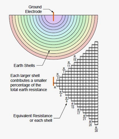
Earthing is used to protect both human and  equipment's  from abnormal currents. These abnormal currents will get dissipated safely when properly conducted to earth via the electrode. There are three components to the resistance:- 1.       Resistance of the electrode materials 2.       Contact resistance between the electrode and the soil surrounding it 3.       Resistance of the surrounding earth. The contact resistance between earth and the electrode is minimal if the electrode materials Cleaned properly and unpainted.  Even if steel get rusted even then rusted steel ground rods have little contact resistance because the iron oxide readily soaks up water and has less resistance than most soils. It has been found that the resistance of the surrounding earth will be the largest of the three components as described above. A proper earthing system generally works on the system that an earth electrode system buried in the earth radiates current in all directions which will get dissipa

Digital Multimeter working principle; DMM working

Image
Digital multimeters are most widely used in every industry as it used for measurement of Voltage, Current, Resistance, Capacitance and various other parameters. DMMs have been available for very several years. Yet it is still challenging to locate advice about how a digital multimeter works. The operation of a digital multimeter is comparatively uncomplicated, although there are obviously differences in how digital mulimeters work if they're from different makers.Despite this, there are several similarities and some general principles of how digital multimeters work. Fundamentals of how a DMM functions The key process occurring within a digital multimeter for any measurement is that of voltage measurement. All other measurements are derived from this basic measurement. So the best technique for understanding how a digital multimeter functions is in understanding this procedure. There are many kinds to digital converter, ADC. Nonetheless the one that is most widely used DMMs in di

Surge Arresters; Surge arrester works principle; Surge Suppersors

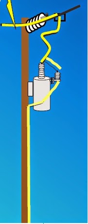
We have discussed about Lightning arrester now lets discuss about surge arrester. Although they both have same principle of working. In this article we will discuss about brief details about arresters. First you must know about what arrester is ?? Answer to this question is that The arrester provides a low-impedance path to earth from transient voltage or a lightning strike and after that restores to an ordinary operating conditions. For simplicity you may consider a surge arrester similar to your relief valve on hot water heater or a boiler. High pressure will be released by it until there is a standard operating state achieved. The safety valve is prepared for another operation, when the pressure is returned to standard. Whenever there exist a high voltage (greater than the standard line voltage) on the line, the arrester drains off the extra voltage and promptly furnishes a route to ground and therefore limits. The arrester then prevent any additional flow of current as clear from t

Lightning Arrester Working Priciple; How Lightning Arrester works

Image
Lightning arrester is nothing more than a spark air gap with one side connected to a line conductor and the other side connected to earth. When the line-to-ground voltage reached the spark-over level, the voltage surge would be discharged to earth. The modern metal oxide arrester provides both excellent protective characteristics and temporary overvoltage capability. The metal oxide disks maintain a stable characteristic and sufficient non-linearity and do not require series gaps Current level in a Lightning Stroke, Current levels in lighting stokes is as below:- 1 percent'of strokes exceed 200 000 A 10 percent of Strokes Exceed 80 000 A 50 percent of Strokes Exceed 28 000 A 90 percent of Strokes Exceed 8 000 A 99 percent of Strokes Exceed 3 000 A The current in the majority of earth flashes is from the negatively charged cells and the flash current is, thus, a negative Row from cloud to earth there will be lighting strokes from positive charged cell but they are very few ones. So

Car AC working principle; Car Air conditioner

Image
Air conditioning as names 'states' the conditioning of air. Air conditioner not only cools down the air , but also reduces humidity, or the moisture content. All air conditioners work exactly the same manner whether they're installed in a a vehicle, or in a building. Freezer or the refrigerator is an air conditioner too. Air conditioning is an area inside it's own right, but we'll adhere to the principal points or an automobile's air conditioning and the main parts used and a number of hints to keep the air-con system running properly. There's energy used in removing moisture and the heat from the air in the automobile, and petrol is consumed by this because of the additional engine load. The main principles of air conditioning are Evaporation and Condensation, then Compression and Expansion. To physicists and the engineer they talk of thermodynamics - but it 'll be explained by us in our own manner here:  Below is schematic diagram for explaining how ac

Overload relay working principle and features of thermal motor overload

Image
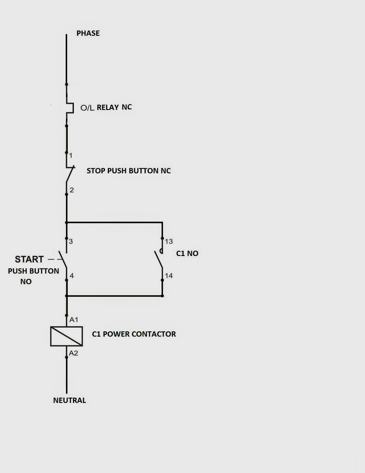
Thermal overload relays play a very important for protection of motors and generators both. It should be very interesting to know how an Thermal overload works as all over load relays have same working principle. Thermal motor overload protection relays feature bi-metal strips jointly with a trip mechanism in a casing made of insulating material. Whenever there is overload The motor current heats the bi-metal strips, making them bend and activating the trip mechanism after a particular interval which is based on the current- setting. The release mechanism actuates an auxiliary switch that breaks the motor contactor's coil circuit as shown in circuit diagrams below. A changing position indicator signals the condition "tripped". Above diagrams shows where overload is connected in motor circuit. You may see that in Control circuit overload relay comes first in line but in power circuit it comes at last in line. Question arises why this is done?? This all done because to prot

DC Motors working principle; Direct current motors

Image
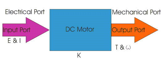
There are two types of supplies and there are two types of motors known as :- 1. AC Motors 2. DC Motors Here we will discuss about DC motors working principle. These DC motors works on the principle that when there is a current carrying conductor put in a magnetic field it will experiences a torque. This is called motoring activity.  If the direction is reversed. Then this will act as a generator. Electrically structurally and construction wise a direct current generator is just the reverse, although it is precisely just like a DC motor.  Block diagram for the same is shown below. Here we derive mechanical energy in the output signal interface and provide electrical energy to the input signal interface. i.e. is called as DC motor and for DC generator it is reverse i.e. mechanical at I/p and we get electrical energy at the O/p. Direction of rotation of DC motor is given by Fleming left hand rule The direct current motor's input and output signal interface variables are connected by