Posts

Showing posts with the label arduino

Wireless voltmeter using Arduino and RF 433MHz receiver and transmitter

Image
In this project i showed you how to make a wireless voltmeter using arduino and RF 433MHz receiver and transmitter. You can use this code and concept for many other projects, any project which used sensor with analog voltage output to sense temperature, gas leakage or light , etc. For example you can put a LM35 temperature sensor rather than potantiometer, you just have to putting its formula which convert LM35 output pin voltage to exact temperature. You also can make a wireless AC or DC power meter by doing some change in code and hardware (using hall effect current sensor and single phase voltage sensor). This type of RF module has distance range up to 200 meters according to datasheet but when i bought this RF module from Aliexpress its distance rang was very low, but i set its adjustable RF coil very carefully and i get very higher distance rang.(Don't play with RF coil if your module works good), You also have to use a 6 inch antenna to increase distance range to max as possi...
Power factor measurment using Arduino

Image
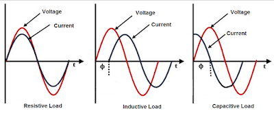
In this project i used arduino and XOR gate to power factor measurement. What is power factor? Power factor is a number between 0 and 1 refers to phase shift between voltage phase and current phase in AC appliance. How to measure PF with Microcontroller (Arduino)? To measuring power factor with microcontrollers in first we used Op-Amp to zero cross detection to find the phase shift between current and voltage phase, the op-amp convert the sine wave signal comes from CT and PT with different amplitude to square wave with about 4v amplitude, then we connect these two square wave to XOR gate inputs.  XOR gate output will be 1 just when the input have different signal so when the load is resistive XOR gate output is 0 because both voltage and current phases start and ends in the same time, but when the load is inductive or capacitive XOR output is 1 because there are phase shaft between voltage and current, Hence we can find the power factor by measuring the "ON-time" of XOR out...

Arduino 220v AC dimmer with remote control with code

Image
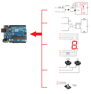
This Arduino project help you to control brightness of a 220V dimmable lamp or speed of ceiling fan (or any other electric motor) with an IR remote control using Arduino. Max. power which can controlled with this dimmer depend on triac model.(BT136 can bear 4A according to Datasheet). This project consist of 4 basic parts: 1-Microcontroller(Arduino) 2-Zero-cross detector(Bridge and Optocoupler) 3-Display(7Segment) 4-Phase angel controller(Tiac and Triac driver) The load can controlled by Up and Down bush button or with IR remote controller.  Circuit diagram:   Parts list: Arduino UNO(or other version) Optocoupler pc817 Triac driver MOC3021(Or any other Random-phase triac driver) 1 Digit 7 Segment common cathode Triac BT136 Diode bridge(4pcs 1N4007) Push bottom(4pcs) Resistor 100K(2pcs) Resistor470 ohm (2pcs) Resistor 330 ohm Resistor 100 ohm 1W Resistor 10K Capacitor 100nF 400v IR receiver 1830B Important NOTES: 1- You have to using only RANDOM-phase triac driver such as MOC ...

220V Auto room light switch using Arduino and Lazer (Visitor counter)

Image
Many peoples forgets the Room lamps in running state when nobody in the room, this causes increasing electric bill or battery energy losing in solar home. This Arduino project is a visitor counter that turns OFF the lamp when nobody in the room automatically, it also can used for lamps of bathroom, toilet, kitchen, etc. Visitor counter can makes by using different types of sensors, such as IR ray, Ultrasonic, Avoidance sensor, Laser ray, etc. Here i used Laser because the laser has long distance range, Avoidance sensor is very easy to use but its distance rang is lower than 30cm. You can make this project with LCD display for showing the numbers of people in the room but as you can see in the video i don't used display because its not important for me, any way the code is same with or without display. This project help to power consumption optimizing.  Parts list: Arduino board  1 Channel Relay module Laser diode(2 pcs) Light sensor modules(2 pcs) Adapter 5v 200mA If you want ...

AC 220V Frequency counter using arduino

Image
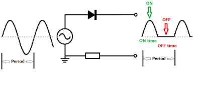
In this project i used Arduino and some other electronic components for AC mains frequency measurement. Since Frequency is equal to: 1 divided by time period, so in first we should measure the time period. Time Period is the time of one full wave in AC voltage, means positive half wave+negative half wave. Here i used optocoupler for detecting the frequency of AC voltage. 47K resistor decrease the current to about 5mA for running the optocoupler and one diode for half wave rectification  So the arduino here calculate the ON time and OFF time of optocoupler that connected to Pin 13 in arduino board, then divided 1 by ( ON+OFF ) Time for give the frequency.  Since in arduino code the time always must insert as millisecond so we devide 1000 by ON+OFF Time for give the frequency. The circuit 100% insulated from mains voltage and can not be harmful for your arduino board. You can use any other available optocoupler rather than 817B.  Parts list:  Arduino board LCD display ...

Arduino Gas leakage sensor with LCD display

Image
By this Arduino project you can display the amount of LPG and methane gas leakage on 16x2 LCD display. I set the program to run the buzzer when the value become 15 or more, you can change this level. you have to use 150 to 220 ohm resistor to protect the backlight LED of display. Parts list: LCD display 16x2 buzzer Resistor 220 ohm MQ-4 gas sensor module  Potentiometer 1K Connecting wires Arduino board #include <LiquidCrystal.h> LiquidCrystal lcd(7, 8, 9, 10, 11, 12); int potPin = A4; int potValue = 0; int buzzer = 6; void setup() {     lcd.begin(16, 2); // lcd rows and columns     lcd.print("GAS SENSOR");     pinMode(6, OUTPUT); } void loop() {     potValue = analogRead(potPin);        lcd.setCursor(0, 1);     lcd.print("Value = ");     lcd.print(potValue);     delay(1000);     lcd.print(" ");     delay(1); if (potVal...

Turn ON-OFF electric appliances using any IR remote control

Image
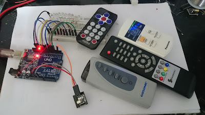
By this Arduino project you can run any electric devices (AC and DC) by using any IR remote control in your home. (remote control of TV, satellite, air conditioner, etc) Since each IR remote control button have certain frequency, so you have to determine that and put that in the code.   You have to follow this steps: 1-connect your relay module (or LEDs) and infrared receiver module to your Arduino board as shown in following figures 2-then upload the code (in below of this page) to your Arduino board and open the serial monitor 3-then press any button of your remote control (put the remote toward the IR receiver) 4- put the number that appears in serial monitor (in prior step) in your code and repeat this work for each buttons then upload the code again  5-Now it is ready to use as you can see in following video, when you press the button key, the load that connected to that pin turn ON and by other press it be turn OFF. Note: you have to add IRremote.h file to your Arduino l...

RF remote control module review

Image
This RF remote control based on IC PT2272-M4, can used with or without Arduino. it is very easy to use. There are one channel, two and four channels remote control module in the markets. There are 3 types modules in terms of switching method: 1-If the module made by IC PT2272- M4 , that means the output will be HIGH when you push the button and be LOW when you release the button. 2-If the module made by IC PT2272- T4 , that means the output will be HIGH when you push the button and be LOW when you press the button again. 3-If the module made by IC PT2272- L4 , that means the A-output will be HIGH when you push the A-button and be LOW when you press B-button. By this remote control you can run any load from 50 to 100 meters. You have to add a transistor and relay(as figure) for running 110/220v AC or some DC power LEDs.   Receiver module: Based on PT2272-M4 chip Working frequency: 315MHz Working Voltage: DC 5V Static current: 4.5mA Pin assignment: D0: Output 0 D1: Output 1 D2: Outpu...

Password lock with only one button switch using Arduino

Image
Electronic locks with password always had a keyboard for inserting the code, but following lock used only one button switch. The code must inserts by pressing the button switch 5 times but with certain delay between each pressing, as you can see in programming code i sets this delay time 1 second delay between four first codes and 5 seconds for two last codes, you can change this code by changing that delay times in programming code. After inserting the correct code the load that connected to pin10 runs for 3 seconds, you can change this delay time in code. If an incorrect code inserts, the red LED turns ON also for 3 seconds. Last important note is the "tolerance" stage in programming code, i sets it on 0.4, that means the delay time between each two pressed buttons acceptable 40% more or lower than the delay time that you write it in the programming code, so 600 to 1400 milliseconds can accepted rather than 1000 milliseconds, or 3000 to 7000 milliseconds can accepted rathe...