Posts

Showing posts from April, 2016

Phone ringer circuit

Image
This is simple phone ringer circuit using IC 4060. Can run it by 5 to 12v and its power consumption is very low, lower than 10mA. You can use any other PNP transistor rather than S9012. Parts list: IC 4060 Transistor S9012(3pcs) Capacitor 3.3nF Resistor 13k (3pcs) Resistor 100k Potentiometer 100k Buzzer

Sequential LED flasher using IC 4017 (KNIGHT READER)

Image
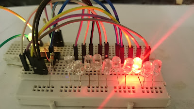
This is a beautiful sequential LED flasher (LED chaser) that also called KNIGHT READER CIRCUIT. Flashing speed can changed by changing the value of capacitor or 33K resistor.  The circuit run by 5v and draw very low current lower than 10mA. You can run the circuit by 12v battery but you have use 1K resistor rather than 470ohm resistor to LED protection. Parts list: IC4017 IC555 Resistor 470 ohm Resistor 33K Diode 1N4148(8pcs) Capacitor 2.2uF LEDs(11pcs)  

Arduino Gas leakage sensor with LCD display

Image
By this Arduino project you can display the amount of LPG and methane gas leakage on 16x2 LCD display. I set the program to run the buzzer when the value become 15 or more, you can change this level. you have to use 150 to 220 ohm resistor to protect the backlight LED of display. Parts list: LCD display 16x2 buzzer Resistor 220 ohm MQ-4 gas sensor module  Potentiometer 1K Connecting wires Arduino board #include <LiquidCrystal.h> LiquidCrystal lcd(7, 8, 9, 10, 11, 12); int potPin = A4; int potValue = 0; int buzzer = 6; void setup() {     lcd.begin(16, 2); // lcd rows and columns     lcd.print("GAS SENSOR");     pinMode(6, OUTPUT); } void loop() {     potValue = analogRead(potPin);        lcd.setCursor(0, 1);     lcd.print("Value = ");     lcd.print(potValue);     delay(1000);     lcd.print(" ");     delay(1); if (potValue>15) {     digitalWrite(6,HIGH);     delay(1000);   } }

Turn ON-OFF electric appliances using any IR remote control

Image
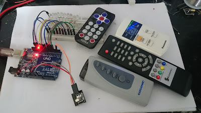
By this Arduino project you can run any electric devices (AC and DC) by using any IR remote control in your home. (remote control of TV, satellite, air conditioner, etc) Since each IR remote control button have certain frequency, so you have to determine that and put that in the code.   You have to follow this steps: 1-connect your relay module (or LEDs) and infrared receiver module to your Arduino board as shown in following figures 2-then upload the code (in below of this page) to your Arduino board and open the serial monitor 3-then press any button of your remote control (put the remote toward the IR receiver) 4- put the number that appears in serial monitor (in prior step) in your code and repeat this work for each buttons then upload the code again  5-Now it is ready to use as you can see in following video, when you press the button key, the load that connected to that pin turn ON and by other press it be turn OFF. Note: you have to add IRremote.h file to your Arduino library, D

12v DC latching ON-OFF touch switch by one touching plate

Image
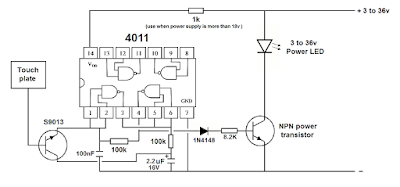
By this circuit you can run 3 to 36v LED or other DC load by touch. the circuit used only one touching plate, its better to use small size plate such as 1cm x 1cm aluminum foil. 1 kilo ohm resistor must used when the power supply is more than 15 or 18v, for limiting the voltage of IC4011. Touching time for turning ON or OFF must be lower than 1 second. You can make this circuit for AC load. Parts list: IC4011 NPN power transistor Transistor S9013 Diode 1N4148 Resistor 100K(2pcs) Resistor 1K Resistor 8.2K  Capacitor 100nF Capacitor 2.2uF 16v Power LED 3 to 36v

Simplest LED chaser using IC4017(without timer IC)

Image
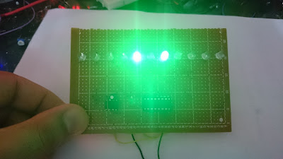
LED chasers that using IC4017 always contain a timer ic for making clock pulse, but this circuit used a flashing RGB LED as a pulse source, so this is simplest, smallest and cheapest LED chaser with 10 LEDs. This circuit can run with 9v battery and draw only 20mA.  Parts list: IC4017 LEDs(10pcs) Flashing LED Resistor 470 ohm Resistor 330 ohm Battery 9v

220v ON-OFF latching touch switch with only one touch plate

Image
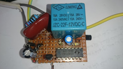
By this circuit you can turn ON-OFF an electric appliance up to 10A by touch.  You can use any other NPN transistor rather than S9013. Its better to use small plate for touching plate such as 1cm x 1cm. Touching time for turning ON or OFF the load must be lower than 1 second. Parts list: IC 4011 Transistor S9013(2pcs) Diode 1N4148 Diode1N4007 Zener diode 12v 1W Bridge diode 1A Relay 12v Capacitor 470nF 400v Capacitor 220uF 35v Capacitor 2.2uF 16v Capacitor 100nF Resistor 100k(2pcs) Resistor 270 ohm 1W Resistor 8.2k Note: Don't touch the circuit when it connected to electric line (exception certain touch plate).

RF remote control module review

Image
This RF remote control based on IC PT2272-M4, can used with or without Arduino. it is very easy to use. There are one channel, two and four channels remote control module in the markets. There are 3 types modules in terms of switching method: 1-If the module made by IC PT2272- M4 , that means the output will be HIGH when you push the button and be LOW when you release the button. 2-If the module made by IC PT2272- T4 , that means the output will be HIGH when you push the button and be LOW when you press the button again. 3-If the module made by IC PT2272- L4 , that means the A-output will be HIGH when you push the A-button and be LOW when you press B-button. By this remote control you can run any load from 50 to 100 meters. You have to add a transistor and relay(as figure) for running 110/220v AC or some DC power LEDs.   Receiver module: Based on PT2272-M4 chip Working frequency: 315MHz Working Voltage: DC 5V Static current: 4.5mA Pin assignment: D0: Output 0 D1: Output 1 D2: Output 2

Mailbox letter indicator circuit

Image
This circuit help you to indicate existing letters in mailbox without opening the box's door. the circuit based on IC555 and using infrared ray. When postman put a letter in the mailbox, the letter cuts the IR ray between IR transmitter and photo-transistor and turn the transistor S9013 ON that connected to pin2 so pin3 of the IC555 become 1 and run the 7-segment display that set to show POST word. but when no letter in the mailbox the 7-segment show 4 dots (. . . .). When you take your letter from mailbox you have to pushing  RESET button or touch pin6. Power consumption of the circuit is very low, about 10mA to 20mA and can run with a small 9v battery. Parts list: IC 555 Transistor S9013 Transistor S9012 IR LED Phototransistor 1 digit 7-segment- common cathode(4pcs) Note: you can use only four 1digit seven segment and can't use one 4digit seven segment.

12v power LED flasher circuit using RGB flashing LED

Image
Flasher circuits usually using 2 transistors or IC, but this circuit used a RGB flashing LED as flashing pulse generation. You can use any other NPN transistor but must pay attention to its max. switching current, according to current of LED(load) . Parts list: RGB flashing LED Transistor S8050 Resistor 100 ohm Resistor 1k Power LED 12v

1.5v LED flashlight circuit

Image
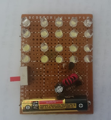
This circuit is an LED flashlight that can run with 1.5 volt AAA battery. this circuit is easiest for beginners because the coil is available in CFL lamps circuit and don't need to make that. I used it for running 20 white LEDs, you can add more. By 20LEDs it draw about 100 to 200mA current from battery. Minimum voltage that need to run LEDs by this circuit is about 0.9v. I test this circuit with different coils and i find the circuit works perfectly with almost all ferrite coils , so you can make that with any available ferrite coil and maybe give better results. Parts list: White LED(20pcs) Transistor S9012 Transistor S9013 Coil 100uH Capacitor 500pF  Capacitor 220uF 10v Resistor 5.6k Resistor 10k Resistor 100 ohm 1.5v AAA battery The following picture show you the coil that available in each CFL lamp, the big coil  in right side give you better result than that circular small coil and maybe can run more than 100 LEDs easily.