Posts

Showing posts from June, 2016

Locked rotor current calculations

Image
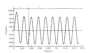
Locked rotor current as clear from its name is the current which motor must overcome for accelerating the motor. When motor is switched on motor isn’t turning and always draws maximum current. When motor starts accelerating this current goes down This locked rotor current is greater than full load current. This locked rotor current required to start the motor depend on the type of motor as well as the specified design voltage required for the motor, typically the higher the voltage, the lower the required amperage or current.   Locked rotor current is 3-8 times the rated current of motor.   "locked rotor current" is the current that would be drawn if the rotor were locked in place so it can't turn. At locked-rotor, each phase of an induction motor stator looks like a series R-L circuit. Locked rotor inrush current graph is as shown below:- Table for NEMA motors NEMA code letters for locked-rotor KVA/HP is below:- Let’s take an example of motor having motor rating of 30 H

Remote Obstacle Finder | Raspberry-Pi.

Image
            Obstacle detection is an important aspect in an Automotive and Automobile System. The basic obstacle detection is already done. Check here . Now, moving on to the next level. The detection and the range of the obstacle is identified remotely. Let us see how it works. Hardware Required Raspberry-Pi ( Refer the first booting of pi here  ) HC-SR04 (Ultrasonic Module) WiFi Adapter (If R-pi2 is used) LED Hookups Protoboard List of Hardware  Software Required                  After booting up your Raspberry pi with Raspbian. The application software which is required to run the program is Python. Python is pre-installed in OS. If you did'n have it do the following. Open Terminal Window and type the following... sudo apt-get update sudo apt-get upgrade sudo apt-get install python3-picamera After setting up your Raspberry pi. Move to the Wiring of sensor and Pi. Wiring Method           Connect the Sensor LED and the R-pi with the help of Hookups and protoboard as shown.  Cir

Transmission tower parts and types of Transmission towers

Image
For transmission of power at High voltage Transmission lines needed to be laid. For laying Transmission lines Transmission towers are most widely used in world. Transmission towers are used for following purposes:- 1.        To separate high voltage conductors from surroundings and from each other. 2.        To keep conductors at sufficient height for safe limits. An overhead transmission line usually consists of three conductors or bundles of conductors containing the three phases of the power system. The conductors are usually aluminum cable steel reinforced (ACSR), which are steel core (for strength) and aluminum wires (having low resistance) wrapped around the core. Tower designing is most important part as towers has to sustain natural calamities.  There are following parts in Transmission towers:- 1.        Tower top 2.        Cross arm 3.        Beam 4.        Insulator string 5.        Fork (K-Frame)/ Cage of Transmission tower 6.        Tower body & Leg of Transmission tow

Cables selection Methodology in electrical systems

1.        Cable Selection according to voltage level: Cables are selected according to voltage level required to be carried by cable. Nominal voltage of the cable is usually expressed in Volts. Cables have nomenclature according to voltage level to be carried through the cables. There are following types of cables according to voltage levels:- Low tension cables:- Cables having voltage level upto 1000V High tension cables:- Theses cables have voltage levels upto 11000V Super tension Cables:- These cables having voltage level from 22KV to 33 KV Extra High tension cables:- These cables having voltage level from 33KV to 66 KV Extra Super voltage cables:- These cables having voltage levels beyond 132 KV  (2) Cable selection according to Current carrying capacity of cables: Cables are selected according to current carrying capacity of cables. This current carrying capacity is known as Ampacity. Cables are usually copper/ Aluminum cables , these cables are selected according to requirement