Posts

Showing posts from November, 2015

Configuration of ( HC-05 ) Bluetooth Module

Image
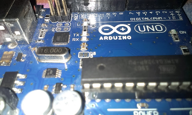
   Yeah. Now we are going to discuss about the configuration of HC-05 Module using the Arduino board. Hardware Required..     ARDUINO (Any board with minimal 328 controller)     HC-05 Bluetooth Module       Hookups About Hardware...   Arduino            Arduino is an Open source Hardware come Software development kit which is used to develop and simulate your Innovative projects. ARDUINO UNO HC-05 Bluetooth Module                  HC-05 embedded Bluetooth serial communication module has two work modes: order-response work mode and automatic connection work mode. And there are three work roles (Master, Slave and Loopback) at the automatic connection work mode. When the module is at the automatic connection work mode, it will follow the default way set lastly to transmit the data automatically. When the module is at the order-response work mode, user can send the AT command to the module to set the control parameters and sent control order. HC-05 Working...         Now make the circuit

Turn ON-OFF electric appliance using Arduino bluetooth HC-06

Image
You can run some electric appliances (AC load) or some LED lamps(DC load) by Bluetooth from your mobile using Arduino. Parts list: Arduino board Resistor 100 ohm(12pcs) Relay module 8 channel or 12 channel LED (12pcs) Bluetooth module HC-06 Adapter 9v 1A IMPORTANT NOTES: 1-RX pin of bluetooth module connected to TX of arduino board and the TX pin of bluetooth module connected to RX of arduino board. 2-You must use 9v adapter rather than 9v battery when you use relay channel module because the battery become empty quickly. 3-When you want upload the programming code to arduino board, first remove the RX and TX pins. 4-Old versions of arduino program can't used for this project so you have to install   new version of arduino program from arduino site for free . Mobile and Bluetooth module pairing steps: 1-In first you must install ArduDroid app. on your mobile from Google play. 2-go to Bluetooth devices menu in your mobile, find the HC-06 and insert the 4 numbers pass-code. usually

Scrolling LCD Using Arduino

Image
          This is my second part. In this I'm directly going to show how to Scroll the characters in the LCD display. If you wanna know about the pin out connections click here .     Working...            Make the connections as shown the earlier post. And upload the written program as shown in the Fig. Code for Scroll       After writing the program Upload it to your Arduino. You can type your own character in double quotes which you want to Display.             Now the character you have typed is scrolled as show in the Fig. Scrolling Display Watch the Video here .. Thank you for your time Feel free to contact me @  abu786sagar@gmail.com

Simplest 220v motion light switch

Image
This circuit is a motion switch that can run 110/220v AC lamp up to 10A. the circuit based on PIR motion sensor module HC-SR501, however you can use any other type but must pays attention to pin configuration(Vout in some modules is the first pin). motion sensor module is very cheap, i bought  it from Aliexpress by only 0.96$ with free shipping. When you buy a PIR motion module usually it not contain LDR so if you want use it for  running the lamp by motion just in dark so you have to add the LDR to that, that is very easy as you can see in the picture there are LDR interface under PIR plastic cover. After making the circuit put it in a plastic box such as ceiling fan regulator box for electrical insulation. Parts list: PIR motion sensor HC-SR501 Transistor 2N2222 12v relay Diode 1N4007 Zener diode 12v 1W Diode bridge 1A Capacitor 220uF 25v Capacitor 330nF 400v Resistor 1k Resistor 270 ohm 2W NOTES: 1-Don't touch the circuit when it connected to electric line. 2-Even after pluggi

Arduino meets LCD 16x2

Image
     LCD stands for Liquid Crystal Display. If it meets Arduino... What would happened? Is now I'm going to show you. Peripherals Involved: ARDUINO UNO (You could use any Arduino board) LCD 16x2 Resistor 10k Protoboard Hookups About Peripherals... Arduino UNO                     Arduino is an Open source Hardware come Software development kit which is used to develop and simulate your Innovative projects. ARDUINO UNO R3 LCD Display 16x2                 As seen earlier LCD Liquid Crystal Display is an Electronic display which is used to display the Characters, Numbers and Emoji too... This display is preferred over the Seven Segment display because of it's Economical issues and Special characters Limitation. 16x2 LCD Display Protoboard and Jumper               Protoboard (Usually Breadboard) is an typical Parallel and Serial conducting board which is used to test your prototype. It contains (1-60) Rows and (A-J) Columns of 1mm hole each.              Jumper wire is an normal e

Amazing LED chaser with 12 LEDs using arduino

Image
This is an amazing LED chaser that contain 12 LEDs. Each LED must protect by a 100ohm resistor. the speed of flashing can change by changing the number that written after "delay" in the programming code. void setup(){   pinMode(2, OUTPUT);   pinMode(3, OUTPUT);   pinMode(4, OUTPUT);   pinMode(5, OUTPUT);   pinMode(6, OUTPUT);   pinMode(7, OUTPUT);   pinMode(8, OUTPUT);   pinMode(9, OUTPUT);   pinMode(10, OUTPUT);   pinMode(11, OUTPUT);   pinMode(12, OUTPUT);   pinMode(13, OUTPUT); } void loop(){     digitalWrite(4, HIGH);   delay(100);   digitalWrite(4, LOW);   delay(100);   digitalWrite(4, HIGH);   delay(100);   digitalWrite(4, LOW);   delay(100);   digitalWrite(8, HIGH);   delay(100);   digitalWrite(8, LOW);   delay(100);   digitalWrite(8, HIGH);   delay(100);   digitalWrite(8, LOW);   delay(100);   digitalWrite(2, HIGH);   delay(100);   digitalWrite(2, LOW);   delay(100);   digitalWrite(2, HIGH);   delay(100);   digitalWrite(2, LOW);   delay(100);   digitalWrite(10, HIGH);

Display 4 digits on 7 segments using arduino

Image
You can display 4 digits on the 7segments using arduino. the number must insert in "serial monitor" by PC. NOTES: 1-use 4 resistors 220ohm through digit1, digit2, digit3 and digit4 to protection. 2-7segments is common cathode. /*  4 digit 7 segment LED display common cathode boolean DigitOn = LOW; boolean DigitOff = HIGH; boolean SegOn=HIGH; boolean SegOff=LOW; int DigitPins[] = {2, 3, 4, 5}; int SegmentPins[] = {6, 7, 8, 9, 10, 11, 12, 13}; //looks terrible, but I didn't find a way to copy Arrays or merge them from parts //N is for numbers and NxP is a number with a decimal point behind int BLANK[] = {LOW, LOW, LOW, LOW, LOW, LOW, LOW, LOW}; int N0[]    = {HIGH, HIGH, HIGH, HIGH, HIGH, HIGH, LOW, LOW}; int N0P[]   = {HIGH, HIGH, HIGH, HIGH, HIGH, HIGH, LOW, HIGH}; int N1[]    = {LOW, HIGH, HIGH, LOW, LOW, LOW, LOW, LOW}; int N1P[]   = {LOW, HIGH, HIGH, LOW, LOW, LOW, LOW, HIGH}; int N2[]    = {HIGH, HIGH, LOW, HIGH, HIGH, LOW, HIGH, LOW}; int N2P[]   = {HIGH, HIGH, LOW,