Posts

Showing posts from May, 2016

Turn ON-OFF 220v electric appliances by any IR remote control

Image
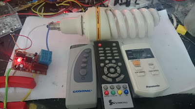
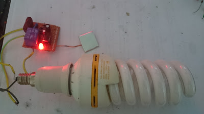
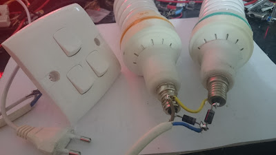
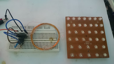
By this circuit you can turn ON and OFF an electric appliance up to 10A by any IR remote control such as remote control of TV, satellite, air conditioner ... etc. Red LED run when the load is turn OFF, it help you to find the switch position in dark. I put here two circuits, they are similar but the first contain a transformerless power supply circuit to convert 220v to 12v and 5v for running the 12v relay and the IC, but the second circuit is easier to make because used a 5v mobile charger to running the circuits by 220v. Parts list: IC 4017 IC 7805 Transistor 2N2222 Transistor S9012 Diode 1N4007 Bridge diode 1A Zener diode 12v 1w LED IR receiver 1838A Capaciror 470nF 400v Capacitor 220uF 16v Capacitor 0.47uF Resistor 270 ohm 2w Resistor 1K Resistor 100K Resistor 47 ohm Resistor 220 ohm Relay 12v

High Tension Cables and its types; HT cables

HT cables are integral part of electrical systems. Electricity is always transferred through HT cable/ Conductors. So it becomes very important to know about HT cables. HT cables are usually XLPE i.e. cross linked polyethylene cables.  Let’s discuss about HT cables used in electrical systems. There are following types of High voltage cables There are two common HT cables are used: (a)     Single conductor:- These cables consisting of one conductor per cable or three cables for a three-phase system. (b)    Three conductor These cable consisting of three cables sharing a common jacket. There are fe'w visible differences between HT cables but HT cables are same there are following parts of HT cables: (i)                  Conductor (ii)                Strand shield (iii)              Insulation (iv)              Insulation shield system (semi-con & metallic) (v)                Jacket. These components are vital and must be needed to be understood in order to make a dependable ter

220V ON-OFF Latching touch switch by one touch plate only

Image
This is second 220v touch switch that i made. the first one was made by IC4011. Touching plate completely insulated from the main supply and can't be dangerous. Red LED allowing you easily to locate the switch in the dark, it be turn OFF when the AC lamp running ON. The touching plate must touch for 1 second for turning the load ON or OFF. You can't use very big touching plate for this circuit and the wire of touching plate must be short as possible. This circuit can run up to 10A load. Parts list: IC555 Bridge diode 1A Diode 1N4007 Zener diode 12v 1W Transistor 2N2222 Relay 12v LED Resistor 1K Resistor10K(3pcs) Resistor 270ohm 2W Capacitor 220uF 16v Capacitor470nF 400v Capacitor 47uF Note: Don't touch the circuit when it connected to the main voltage, even after power separating there are some remaining voltage in the capacitor that can give you shock.

LED chaser with only one IC555

Image
This circuit is a simple LED chaser, (Bike Turning Signal Circuit) used IC 555 and 5 transistors. Here we used IC 555 as astable multivibrator to running the transistors. Flashing speed depend on both capacitors. 1K resistors used for each LED as protection. The circuit run with 12v and draw 40mA current when all LEDs be turn ON. Parts list: IC555 LEDs(5pcs) Transistor S9013(5pcs) Diode 1N4148 Capacitor 470uF Capacitor 100uF Resistor 1K (6pcs) Resistor 4.7K (2pcs) Resistor 10K (2pcs) Resistor 680 ohm

Roulette circuit with touch switch using IC4017

Image
Some games need to pick a random number. this circuit is a roulette with touch switch using IC4017 and IC555. When you touch the wires, LEDs moving speed up and when release them slow down and stop on a number. Flashing speed of LEDs depend on 1uF capacitor and time period between LEDs speed up and stopping depend on 0.47uF capacitor, so you can changes them by other value if you want to change that speed. You can run this circuit by 5 to 12v and power consumption is very low (lower than 10mA). Parts list: IC4017 IC555 Transistor BC557 Capacitor 1uF Capacitor 0.47uF Capacitor 100nF Resistor 3.9M (3 pcs) Resistor 1K Resistor 13K Resistor 330R ohm for 5v power supply 680 ohm for 12v power supply LEDs (10 pcs)

2 Lamps, 2 switchs, 1 wire

Image
When you have a pair of N and L wires and want to turn ON-OFF two lamps SEPARATELY , you have to add third wire, adding third wire for second lamp on the workbench is easy, but that is very hard or impossible if your wires are inside the wall. This is a very very simple idea for solving a big problem. you just have to using 4 diodes. First 2 diodes are responsible of running first lamp and another 2 diodes responsible of running second lamp. In following video i used 3A diodes(1N5408), but 1A diodes such as 1N4007 are enough. Since diodes run the load just in half AC cycle so the lamp give half luminescence because it will consumed half power, for this reason we have to add an capacitor parallel with the load(Lamp) as you can see in following pic. After adding the capacitor this problem solved, following fig. shown the power consumption of 100W lamp before using capacitor(in left) and after using the capacitor(in right) in this circuit.

Wireless power transmitter using IC555

Image
This is a wireless power transmitter that used IC 555 and power transistor. I used it for running 36 white LEDs. You can use any other NPN power transistor instead of 13003. Both coils are 30 turns enamelled wire 30 SWG with 5cm diameter. 10 ohm resistor that placed between base of transistor and pin3 of IC, can replaced by 5 to 75 ohm resistor or jumped, if you jumped it the max. distance range between two coils increased.(power consumption also increased) The circuit run by 3v battery and power consumption is 80 to 270mA. Parts list: IC555 Transistor 13003 Coils 30 turns, 5cm diameter, 30 SWG wire Capacitor 3.3nF Capacitor 47nF Resistor 1k Resistor  10 ohm Resistor 10k LEDs Battery 3v