Posts

Showing posts from September, 2014

Induction Motors Torque Equation; Torque equation

Image
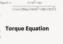
Torque equation for the Induction motor is as given below:- As we see from the above that Torque equation is Directly proportional to square of the voltage. Factors affecting the speed-torque characteristics of an Induction motor :  The speed-torque characteristics are affected by various factors like applied voltage, R 2 ’ and frequency. (a)  Applied voltage  :  We know that T  ยต  V 2 . Thus not only the stationary torque but also the torque under running conditions changes with change in supply voltage. (b)  Supply frequency  :  The major effect of change in supply frequency is on motor speed. The starting torque is reduced with increase in frequency. (c)  Rotor resistance  :  The maximum torque produced does not depend on R 2 ’. However, with increase in R 2 ’, the starting torque increases. The slip at which T max  is reached increases too which means that T max  is obtained at lower motor speeds.

Slip Ring induction motors starting; Slip ring induction motor starter

Image
Starting Of Slip Ring Induction Motors Slip ring Induction motors had external resistance connected in line. These motors are usually started with full line voltage applied across its terminals. During starting of slip ring induction motors the value of starting current is adjusted or kept minimum, by increasing the resistance of the rotor circuit.  The external resistance is connected in star and kept at maximum during starting so to minimize starting current. By increasing the rotor resistance it will not only reduces the rotor current but the stator current too. This means that whenever a resistance is added in rotor circuit that will leads to reduced starting current. Thus because of this, the starting torque is increased due to the improvement in power factor. Usually resistance is added during starting and slowly made out of circuit when motor attains the speed and this resistance is disconnected by using a contactor in line.  Slip ring can be taken in line by using manually also

DOL, Star-Delta, VFD, Soft- Starters, Auto Transformer Starters advantages and disadvantges

The advantages/disadvantages of different types of  motor starters  like :- 1. Direct online starter 2. Star/ delta, 3. Korndorfer  Auto transformer starter 4. Primary resistance/reactance 5. Shunt capacitance 6. Slip ring 7. VFD 8. Soft Starter DOL (Direct Online Starter)   Advantages:- 1. Simple start up  2. Very Low Maintenance cost. 3.  Ease of operation. 4. Very Simple Circuit 5. Very Low initial cost. Disadvantages:- 1. Very high voltage drop during Starting. 2. Very High starting current 3. Very low starting period duration 4. Less power saving. 5. Not feasible for motors above 10 KW.  Star/delta decrease the starting current to 1/3 but required many relays for control change between start connection then to delta.  Slip ring starters are used for starting slip ring motors and these consists of separate slip ring for starting. Main disadvantage associated with these starters is their very high maintenance cost. Auto transformer used for MV application by connect less voltage

Power plants in electrical systems and Power stations working principle

Power Plant Everyone electrical engineer has very much interest in power generation. Now let's study 1st what is power plant??? A power plant is that industry where power get generated. Power generation usually takes place in Megawatts. From there power is power transmission is done and provided at palaces as per requirements. Power plants requires huge land and water that is why power plants are usually located at a far away distance from main city. For this reason, a power generating station has to not only take care of efficient generation but also the fact that the power is transmitted efficiently over the entire distance. And that’s why, the transformer switch yard to regulate transmission voltage also becomes an integral part of the power plant. At the center of it, however, nearly all power generating stations has an A.C. generator or an alternator, which is basically a rotating machine that is equipped to convert energy from the mechanical domain (rotating turbine) into el

Chemical earthing; Maintenance free earthing; Gel earthing

Chemical earthing is now becoming popular within industry as they have long life without any maintenance and also they provide good resistance value. There isn't any different method for making Chemical earthing. There is only difference in type of treatment used in making earthing pit. Treatment used in earthing pits also know as artificial treatment of earthing pits Multiple rods, even in large number, may sometime fail to produce an adequately low resistance to earth. This condition arises in installations involving soils of high resistivity. The alternative is to reduce the resistivity of the soil immediately surrounding the earth electrode. To reduce the soil resistivity, it is necessary to dissolve in the moisture, normally contained in the soil, some substance which is highly conductive in its water solution. The most commonly used substances are sodium chloride ( NaCl ), also known as common salt, calcium chloride ( CaClj ), sodium carbonate ( NasCOs ), copper sulphate ( Cu

Working principle of MCB; Miniature arc circuit breaker

Image
MCBs or Miniature Circuit Breakers are electromechanical devices which protect an electrical circuit from an over-current.  Where Miniature circuit breaker means minimum arc circuit breakers. The over-current, in an electrical circuit, may result from short circuit, overload or faulty design. A MCB is a better alternative other than Fuse since it does not require replacement once an overload is detected. Unlike fuse, an MCB can be easily reset and thus offers improved operational safety and greater convenience without incurring large operating cost. MCB is most widely used for industrial and domestic applications i.e. for lighting loads and small motor loads. MCB or Miniature Circuit Breakers The working principal of MCB is simple. An MCB functions by interrupting the continuity of electrical flow through the circuit once a fault is detected. In simple terms MCB is a switch which automatically turns off when the current flowing through it passes the maximum allowable limit. Generally M

Vacuum Circuit breaker working principle and advantages of VCB

Image
As discussed earlier circuit breakers working principle of type of arc quenching medium during breaking of circuit breaker.  In case of Vacuum circuit breakers arc quenching takes place in vacuum. The technology is suitable for mainly medium voltage application. For higher voltage vacuum technology has been developed but not commercially viable. The operation of opening and closing of circuit breaker contacts and associated arc interruption take place in a vacuum chamber in the breaker which is called vacuum interrupter. The vacuum interrupter consists of a steel arc chamber in the centre symmetrically arranged ceramic insulators. The vacuum pressure inside a vacuum interrupter is normally maintained at 10 - 6 bar. The material used for electric current carrying contacts plays an important role in the performance of the vacuum circuit breaker. CuCr is the most ideal material to make VCB contacts. It requires minimum maintenance compared to other circuit breaker technologies. Advantage