Posts

Showing posts from June, 2015

Power factor variation with load;Why Power factor low during Starting of Motor?

Image
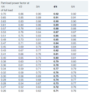
During starting of Induction motor , motor draws very high current as power factor at the start is very low. Power factor is very low because the magnetizing component of current  is very high at starting. At Start Magnetizing component current is very high as it has to overcome the reluctance offered by air gap between stator and rotor. This leads to higher current withdrawal during starting. You can also say that angle between core-loss component and net current increases. As power factor is angle between core-loss component and net current, then there will be decrease in power factor. During starting Power factor starts from zero and keeps on increasing and will be maximum at full load current. Rated Power factor of motor will be achieved at Rated current of motor. Usually it is power factor at start is considered as 0.2. Motors usually have rated Power factor between 0.80 -0.90. Power factor varies as per load connected to the motor. Chart for the same is shown below:- From above

Running LED by 220v

Image
This circuit is simple way to running some parallel LEDs by direct 220v. The output current depend on the capacitor and the resistor and can calculate from following equations: The series capacitor in AC current work as a resistor called (Capacitive reactance) in first you have to find it from following formula: Xc = 1 ÷ (2π * f * C) Where: Xc is the Capacitive reactance in ohm f is the frequency of mains voltage in Hz(usually 50 or 60Hz) C is the capacitor value in Farad V is mains voltage Then add this Capacitive reactance to the resistor to find total resistor (Z): Z= √( (Xc^2)+(R^2) ) Now you can use Ohm's law for finding output current: I = V ÷ Z EXAMPLE: Find the output current for following circuit? Xc = 1 ÷ (2π * f * C) Xc = 1 ÷ (2π * 50 * 0.0000001) Xc = 31847.1 Ohm Z= √((Xc^2) + (R^2)) Z= √((31847.1^2) + (150^2)) Z= 31847.4 Ohm I = V ÷ Z I = 220 ÷ 31847.4 I = 0.00697A = 7mA Since 5mm LEDs need to 5 to 10mA for running so this capacitor and resistor value is enough to runn

How to install and programming an LED sign board

Image
Each LED board contain 3 basic parts: LED module, controller, power supply LED module LED modules can connect together to make a big display. there are single color LED modules, 2colors and full colors(RGB) LED modules. since traditionally LEDs when leaves in sunlight for long time loss its first brightness, so that modules make by special LEDs that have higher resistance to sun ray.   Controller controller (some time call mother board) contain LED display driver, memory and back up battery. Power supply power supply is a 5v regulated adapter and its current is between 1A to 50A or more (according to number of modules that make bigness of display) Note: connecting + and - in reverse causes damage for both controller and LED modules. Programing process For programming the LED board first must install "HD2013" program on your computer. You can download it from following link( password=168 ): https://drive.google.com/open?id=0B4jg9KxpTKGTeWZzbU11Yl82cG8 when installing comple