Earth Pit Resistance measurement method; Fall of Potential method
Earthing is used to protect both human and equipment's from abnormal currents.
These abnormal currents will get dissipated safely when properly conducted to earth via the electrode.
There are three components to the resistance:-
1. Resistance of the electrode materials
2. Contact resistance between the electrode and the soil surrounding it
3. Resistance of the surrounding earth.
The contact resistance between earth and the electrode is minimal if the electrode materials Cleaned properly and unpainted. Even if steel get rusted even then rusted steel ground rods have little contact resistance because the iron oxide readily soaks up water and has less resistance than most soils. It has been found that the resistance of the surrounding earth will be the largest of the three components as described above.
A proper earthing system generally works on the system that an earth electrode system buried in the earth radiates current in all directions which will get dissipated at some distance away depending on the soil’s resistance to current flow which is also known as soil resistivity.
Earthing system consists of multiple electrodes buried at distance and are connected in parallel and a grid is formed so as to minimize grid resistance and whenever fault occurs that fault current will flow through grid and ultimately get dissipated.
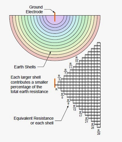
Generally an earth electrode can be thought of as being surrounding by shells of earth, each of the same thickness as shown below. The shell closest to the electrode has the smallest surface area and offers the greatest resistance as resistance is inversely proportional to area. The next shell has larger area then nearest shell so it has lower resistance, and so on. A distance eventually will be reached where the additional earth shells do not add significantly to the resistance.
Earth electrode resistance is measured to remote earth, which is the earth outside the electrode’s influence. A larger electrode system requires greater distance before its influence decreases to a negligible level.
Measuring Earth pit Resistance
Earth pit resistance is measured by using earth pit tester. Which are shown below:-
There is following process by which earth pit resistance can be measured. There are four terminals in earth pit tester described as ;
There is following process by which earth pit resistance can be measured. There are four terminals in earth pit tester described as ;
C1 & C2 known as current terminals, P1 & P2 known as potential terminals.
One current terminal (C1) is connected to the earth electrode under test and the other (C2) to a probe driven in the earth some distance away. The test set injects a current into the earth between the two current terminals. One potential terminal (P1) also is connected to the earth electrode but the other potential terminal (P2) is connected to a separate probe driven in the earth between the electrode and the current probe (C2). The potential probes detect the voltage due to the current injected in the earth by the current terminals. The test set measures both the current and the voltage and internally calculates and then displays the resistance
Resistance= Voltage/ Current
When measuring the resistance of earth electrode systems generally fall of potential method is used.
Fall of Potential Method:-
This method is most widely used to measure earth pit resistance. Procedure for the same is discussed below:-
The basic procedure for the Fall-of-Potential method is to first connect the test set terminals C1 and P1 to the earth electrode under test, connect the test set C2 terminal to a current probe located some distance from the earth electrode and finally connect the test set P2 terminal to a potential probe located a variable distance between. The two probes normally are located in a straight line. At each potential probe location, the resistance is recorded (a form is provided in
1. Connect C1 and P1 terminals on the test set to the earth electrode as shown in fig below
2. Drive a probe into the earth 100 to 200 feet from the center of the electrode and connect to terminal C2. This probe should be driven to a depth of 6 – 12 inches.
3. Drive another probe into the earth midway between the electrodes and probe C2 and connect to terminal P2. This probe should be driven to a depth 6 – 12 inches.
4. Record the resistance measurement.
5. Move the potential probe 10 feet farther away from the electrode and make a second measurement.
6. Move the potential probe 10 feet closer to the electrode and make a third measurement.
7. If the three measurements agree with each other within a few percent of their average, then the average of the three measurements may be used as the electrode resistance.
8. If the three measurements disagree by more than a few percent from their average, then additional measurement procedures are required.


Comments
Post a Comment