Digital DC Voltmeter Using Microcontroller 8051 Mini Project
Digital DC Voltmeter Using Microcontroller 8051 Mini Project
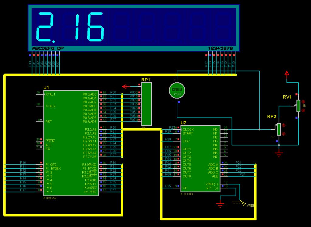
Digital DC voltmeter using Microcontroller or microprocessor is a project in which basically voltage of the system or circuit is measure and 7-segment or display on 16x2 Alpha numeric LCD(Liquid crystal display) This project is best suited for learning of voltage measurement and microcontroller or microprocessor based system from electronics or electrical field person or engineering or diploma student. In this project we are using digital measurement method in which we are uses ADC (Analog to digital convertor) to measure digital form of voltage and then processes this digital value using microprocessor or microcontroller 8051 from Atmel(89s52) then display this digital value on 7-segment or 16x2 Alpha numeric LCD. we can also use other microcontroller or microprocessor manufactures by NXP ARM, Microchip’s PIC18f,PIC12F,PIC16F series…etc., STM series from STMicrotronics , freescale ,AVR etc. instated of Atmel 8051.Some of Microcontroller have inbuilt ADC Analog to digital converter .We are also provided or tested on computer simulation using simulation software Proteus.
 |
| Proteus Simulation-Digital DC voltmeter Using Microcontroller 8051(Atmel 89x52) |
Aim:
Design Digital voltmeter using microcontroller or microprocessor and display on 7-segment or 16x2 LCD(Liquid crystal display)we are using 7-segment in this simulation in Proteus.
Theory:
This introduction makes the link with analog voltage measurement. The digital voltmeters are simply compute digital values from ADC then processed and display on 7 segment.
A key element in processing digital signals is microcontroller. Microcontroller perform direct Manipulations signals. To completely describe digital voltmeter, three basic elements (or building blocks) are needed: an ADC(analog to digital converter 0808), a microcontroller, and a display device. The ADC 0808 has 10 inputs channels and 8-bit digital output
Software:
Keil uvision 3 3.30a
C51 8051 Compiler
Proteus 7.10 Labcenter Electronics
Component and Hardware:
AT89S52 Microcontroller from Atmel
ADC0808 Analog to Digital Converter 8-channel 8-bit Texas Instruments
7-segment Multiples Display
C Code(C Programme):
//*******************************************************
// ******* DC voltmeter ********
//*******************************************************
//Company : www.beprojectidea.blogspot.com
//Controller: 8051 Microcontroller ATMEL
// Compiler : C51 Keil uvision 3 3.30a
//Version : 1.0
//*******************************************************
#include <AT89X52.H>
#define data_point P0 //data bus port
/* ADC0809 control pins */
sbit EOC =P2^0;
sbit ADDA =P2^1;
sbit ADDB =P2^2;
sbit ADDC =P2^3;
sbit OE =P2^5;
sbit START=P2^6;
sbit CLK =P2^7;
/* Global variables */
unsigned char disp[3]={0,0,0};
unsigned char t0count=0;
/* Display function */
void display()
{
unsigned char i,j,k=0x80;
for(i=0;i<3;i++)
{
P1=~0;
P3=disp[i];
P1=~k;
k>>=1;
for(j=200;j>0;j--);
}
P1=~0;
}
/*Function to Read ADC*/
unsigned char ADC0809()
{
unsigned char d;
ADDC=0;
ADDB=0;
ADDA=0;
TR1=1;//enable timer
START=1; START=0; //start ADC
while(EOC==0); //check for EOC to go high
OE=1; //enable output data
d=data_point; //read data
OE=0; //disable adc
TR1=1;//stop timer
return d; //return data
}
void covert(unsigned char x)
{
char code dispcode[]={0x3F,0x06,0x5B,0x4F,0x66,0x6D,0x7D,0x07,0x7F,0x6F};
disp[0]=dispcode[x/50];
disp[0]=disp[0]+0x80;
x=(x%50)*2;
disp[1]=dispcode[x/10]; //first decimal
disp[2]=dispcode[x%10]; // second decimal
}
void main()
{
TMOD=0X21; //Enable timer 0 in mode 1 and timer 1 in momde 2
TH0=(65536-10000)/256; //T0 for 10ms
TL0=(65536-10000)%256;
TH1=256-2; // T1 for 2us
ET0=1;
ET1=1;
EA=1;
TR0=1;
OE=0; //Initilize ADC
START=0;
EOC=1;
while(1)
{
display(); //display data
}
}
void time0() interrupt 1
{
TH0=(65536-10000)/256;
TL0=(65536-10000)%256;
t0count++;
if (t0count==10) //check for 1sec
{
t0count=0;
covert(ADC0809()); //´convert data from adc
}
}
void time1() interrupt 3
{
CLK=~CLK; //ADC clock pulse
}
CONCLUSION
We can measure voltage using digital voltmeter Using Microcontroller 8051(Atmel 89x52) and compare with the analog voltmeter reading which almost accurate and we can further develop other meter in future such as ohmmeter, ammeter etc.we can also use other microcontroller or microprocessor manufactures by NXP ARM, Microchip’s PIC18f,PIC12F,PIC16F series…etc., STM series from STMicrotronics , freescale ,AVR etc. instated of Atmel 8051.Some of Microcontroller have inbuilt ADC Analog to digital converter.
( Full Report)DOWNLOAD
(C Code and Computer Simulation) DOWNLOAD


Comments
Post a Comment