Posts

Obstacle Detection

Image
         The Obstacle detection is the one of the most necessary process in any modes of Transportation. For example in ships, they uses SONAR and RADAR to find the upcoming obstacle. Likewise in Air force they uses RADAR.         Today, I'm going to share the most interesting project called Obstacle Range Measurement. One more important thing is, its going to find the range without being in physical contact to it. List of Hardware... Arduino Controller (Any Version applicable) Ultrasonic sensor (HC-SR04) 16x2 LC Display Module Hookups Protoboard Light Emitting Diode About Hardware Used.        Arduino AT MEGA 2560                          Arduino is an open source hardware/software development board which is mainly came into picture because of it's physical design and economical worth.                     ...

81 LED chaser using double IC 4017

Image
This circuit is LED chaser using double IC 4017 and IC 555 with 81 LEDs. Flashing speed can change by potentiometer. All transistors are 2N3904 but you can use any other NPN transistor. Diode 1N4007 used for inverse power connection protection because IC 555 is very sensitive to - and + power supply reverse connection. 470 ohm resistor used for LEDs protection. you can use different color for each LED column. The circuit can run by 3 x AA battery and power consumption is very low (about 10 to 20mA). Parts list: IC4017(2pcs) IC555 2N3904(9pcs) 10k resistor(10pcs) 470 ohm resistor 3.3k resistor LED(81pcs) Capacitor 1uF 10v 100k potentiometer  Diode 1N4007 1.5v AA battery(3pcs)

Full wave rectifier; Full wave bridge rectifier

Image
Full Wave Rectifier:- Full Wave Rectifier are used to convert AC into DC. Average DC output of full wave rectifier is more than half wave rectifier also ripples are lower in DC in full wave rectifier in comparison to half wave rectifier. Full wave rectifier circuit consists of 2 no. of diodes one for each half cycle. Full wave rectifier circuit is as shown below:- In above circuit secondary winding is center tapped. In this circuit each diode starts conducting when anode terminal is positive with respect to transformer center point. This will leads to conduct both diodes alternately and produces DC in both half cycles of AC. In circuit shown above you can see that there are two diode connected to single resistive load.In Transformer when point 1 get positive with respect to center point 3 diode 1 starts conducting and direction of flow is shown as in figure. Now when point 2 get positive with respect to center point 3 than diode 2 starts conducting in forward direction and direction of...

Advantages of Thermal Power plant

Thermal power plants are the power plants in which coal combustion is used for generating electrical energy. These are also known as steam power plants. There are so many advantages and disadvantages of Thermal power plants as below:- Advantages of Thermal Power plants 1.       Lower Fuel cost:- Main advantage of Thermal power plant in comparison to other power plants is that fuel i.e. coal is very much cheap in comparison to other fuel power plants. 2.      Availability of Fuel:- There is abundant availability of coal and also cost of extraction of coal is quite cheaper. 3.      Lower installation cost:- Thermal power plants installation cost is very much lower than other power plants. 4.      Ease of Installation irrespective of location:- Thermal power plants can be installed anywhere in world as coal used of these power plants can be transported by rail/ road/ ship. 5.      Lower...

Color sensor using arduino and TCS230

Image
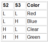
This is color sensor that used TCS230 and RGB LED. color detection in this module depend on S2 and S3 output as follow: L means low and the H means high. you have to use a 330ohm resistor to protect the LEDs. Parts list: RGB LED Resistor 100 ohm Color sensor TCS230 Arduino board /* // TCS230 color recognition sensor // Sensor connection pins to Arduino are shown in comments Color Sensor      Arduino -----------      --------  VCC               5V  GND               GND  s0                8  s1                9  s2                12  s3  ...

How to coding arduino RFID module

Image
RFID can use in many area such as security systems, door key, etc. Any RFID card have special ID so you must set your Arduino board to identify that ID for work only on your card. You have to follow this steps: 1-Connect your RFID module to Arduino board as follow 2-upload the programming code to Arduino board. 3-open "serial monitor" then put your card near RFID module. 4-you must add the number(ID) that shown in serial monitor to the code and upload the code again. 5-Now when you put your card near RFID module the output be turn on and after 5 seconds the output turn off automatically.(this time can change by change the number that written after "delay" in programming code).  // the sensor communicates using SPI, so include the library: #include <SPI.h> #define uchar unsigned char #define uint unsigned int //数组最大长度 #define MAX_LEN 16 ///////////////////////////////////////////////////////////////////// //set the pin //////////////////////////////////////////...