Posts

Showing posts from January, 2016

Lap winding; Simplex and Duplex Lap Winding
Image
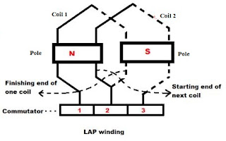
In small DC machines the coils are directly wound in the armature slots. In large DC machines, the coils are performed and then inserted into the armature slots. Each coil consists of a number of turns of wire, each turn taped and insulated from the other turns and form the rotor slots. Each side of the turn is called the conductor. The number of the conductors on a machine's armature is given by                                       Z= 2CN where : Z= numbers of conductors on rotor C= numbers of coils on rotor N= number of turns per coil There are two types of armature windings in DC motors :- 1.   Lap winding 2.   Wave winding. In this article we will discuss about Lap winding:- Lap Winding:- In this winding continuous coils overlap each other. In this winding finishing end of one coil is...
V/f control in Induction Motors; Volts per Hertz control

Image
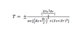
V/f control of Induction motors V/f control is also known as volts per Hertz control . This method is the simplest method for motor control.  In this control method there is not requirement of tuning . This type of control is used where there is requirement for operating the motor up-to 1000 HZ. V/f control has some limitations that is weakness in starting torque and lack of control. By V/f method several motors can be started on single VFD which is not possible with encoder control. When several motors are connected on single VFD all motors can start and stop at same instant and also these motors will run same speed reference. In V/f control method speed regulation is typically 2%-3%. Speed response in that type of control is 3 Hz. Speed response is how well the VFD responds to change in reference frequency.  If this speed response increases then this means that motor will response quicker with the reference frequency change. VFD speed control range in V/f control is in the ...

Krichoff's current law and Kirchoff's voltage law

Image
As we know that Ohm’s law can be applied to circuits where there are resistive circuits only.  Now in electrical systems there are so many complex circuits consisting of lot of other load other than resistive loads. There are some circuits such as Bridge circuits which can’t be solved by using ohm’s law to find out voltages and currents circulating in the circuit. Kirchoff’s current law is used to solve the circuits to find out the current flowing the respective branches. Kirchoff’s current law was given by Gustav Kirchoff in 1845. There are two laws given by Kirchoff naming as Kirchoff’s current law and Kirchoff’s voltage laws. KCL deals with current flowing in a closed circuit whereas KVL deals with voltage sources present in a closed circuit. Kirchoff’s Current Law:- According to this law “Total current entering a Junction or node is equal to current leaving the same junction or node”.  This means that algebraic sum of currents entering and leaving the junction or node is a...

Star to Delta and Delta to Star conversions

Image
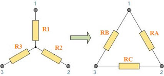
We have seen Star and delta connection is Transformers. Now Star into delta conversions allows us to convert impedances connected together from one type of connections to another. This conversion can be done by using Kirchoff’s circuit laws. Star to Delta Conversion I n three phase power supply Star to delta conversion can be done easily by using these transformations. Circuit for the conversion is as shown below:- There are following formula used for conversion for Star to delta. Resistance RA= R1R2 + R2R3 + R3R1        ……………… (i)                                       R3 Resistance RB= R1R2 + R2R3 + R3R1   ……………… (ii)                         ...

Transformer Losses; Eddy current Hysteresis losses

Transformers are backbone of electrical systems. They are used for stepping up and stepping down the voltages. We will study about losses in Transformer in this article. Losses are necessary evil in electrical systems. These losses can be minimized but could not be eliminated. Transformers are static devices as they don’t have any rotary parts as these are static devices these don’t have any mechanical losses. Now there are only electrical losses which are needed to be looked upon. There are various types of electrical losses in a Transformer, these are as below:- 1.     Core losses 2.     Copper losses 1.     Core losses:- As clear from its name these losses occur in Transformers core and these consists of Hysteresis losses and eddy current losses. Hysteresis losses and eddy current losses both depends upon magnetic properties of Transformer core. These losses are always fixed and also known as no load losses and these don’t depend upon load...

Human Detector

Image
              Surveillance is an most important aspect in all over the places. Say (Banks, Jewelry shops, etc..). Now a days even a small hotels and bakery were using surveillance system to protect their properties.              There are two types of surveillance system were available. They are, Passive surveillance system Active surveillance system             Now our goal is to built a passive surveillance system which will detect the human trace when the system is fired. The materials required for this purpose are.. Hardware required... Any controller board ( Arduino is recommended) Pyroelectric Infrared Sensor (PIR) ("HC SR-501") Servo motor (minimum torque 1.4Kg/m 2 .) 16x2 LCD module Light Emitting Diode (LED) Hookups Protoboard Software required.. Arduino IDE (If Arduino is used) Download Here About Hardware..           Controller board.   ...